Finally we wrote some tiny documentation about RL-AMC-50NP04 along with a reference C source code to interface it from the LPC2138-01 board.
RL-AMC-50NP04 Quick Reference Guide
RL-AMC-50NP04 Reference Source Code
Enjoy it,
Daniel
Robotics, Electronics and some Open Source Weblog
Finally we wrote some tiny documentation about RL-AMC-50NP04 along with a reference C source code to interface it from the LPC2138-01 board.
RL-AMC-50NP04 Quick Reference Guide
RL-AMC-50NP04 Reference Source Code
Enjoy it,
Daniel

Last week, we attended to Campus Party in Valencia. At CampusBot area, some robots competitions took place along the week and we had our line followers ready to fight. The results were pretty good: In the qualifying session on Tuesday we got the fastest two times with our two robots and in the finals on Saturday (being held at Ciudad de Las Artes y Las Ciencias) we managed to win the two first places in the podium !
Here you can see some videos:
Slayer S8 during our first training rounds:
Slayer S8 from a speed view like if it was an F1 camera 🙂 running at more than 2,5m/s:
Slayer S8 at Semifinals Round against the later 4th classified:
It was a great week and the robots performed pretty well in such a speedy track. I might upload some more media when I finish collecting all the videos and pictures from the event.
My colleague Alberto Calvo and me are already thinking in our next robot which will have some kind of inertial control based on gyroscopes and accelerometers. I’ll keep the blog up to date.
Special thanks to our teammates and friends Luis-Ángel Gónzalez and Daniel de la Torre who drove more than 800 km by car just to watch the final rounds and support us (well and to have a nice Paella in front of the beach). Thanks guys!
More to come,
Daniel
 The X-PIC Development System was designed by my colleague and friend Alberto Calvo and me during our studies at University. It is composed of two main boards: X-PIC and X-BOT which I will describe briefly. Our goal was to design a microcontroller based system powerful enough for our Robotics projects. However, we realized that it could be a good idea to design a more generic system which could be used as a small development platform without the need to have a big amount of LED’s, buttons, LCD, switches, jumpers, etc. as most boards use to have. So it is suitable for any projects which require a microcontroller.
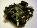
 This is the main board. It has got a PIC16F877A microcontroller at a clock frequency of 20MHz. There’s also an EEPROM serial memory which can be interfaced both externally and through the microcontroller. All the GPIO pins can be easily accessed through the 10-Pin connectors, all of them including VCC and GND signals.
For testing purposes, the board’s got a general purpose button and one LED. It can be programmed through its ICSP connector or through its RS232 interface if a bootloader is previously loaded into its internal Flash memory.
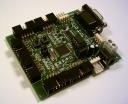
This board was designed specifically for Robotics applications and can be easily connected to the X-PIC board and mounted together. It’s got eight connectors which allow the microcontroller to read their value through selectable digital or analog IO pins. Also it includes two DC Motor drivers to drive up to 4 motors (1A per channel) which make this board suitable for a huge number of Robotics and Electronics applications.
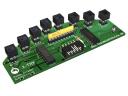 As an extension to this system we designed the X-TRK sensor board specially aimed to Sniffer Robots. It can drive up to 8 IR sensors with just 4 IO pins thanks to its 3 to 8 line decoder. In the picture you can see a 3D version of the board, which has not been yet manufactured (just two home-made protoypes).
You can download all the documentation and schematics in Spanish (sorry for the inconvenience):
Regards,
Daniel
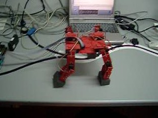
 Slayer is a special robot for me. It was my first line following robot and he has won several National Robotics Contests in Spain (Robolid and X-Treme Robotrackers at Campus Bot).
It’s got just two motors: a servo motor to stick its nose to the line and a DC motor with a small gearbox to achieve the movement.
The control board is based on ATMega32 which is a very nice 8bit microcontroller equiped with 32KB of Flash and 2KB of SRAM memory.
The sensor board’s got 8 infrared sensors and its acquisition is multiplexed to minimize the required IO pins. Also, an ambient light cancelation is performed so that the robot could be able to run in different light conditions and (almost) over any surfaces.
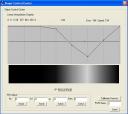
The picture on the right shows the simulator developed to test the algorithm in the PC. It helped me to tune the PID controller and to check all the computation done by the microcontroller. Basically I developed a tiny “RTOS” for the ATMega32 with a cyclic scheduler to achieve the acquisition, computation and PID task in Real-Time at the desired frequency.
At these competitions, the robots have to follow a black line over a white surface as fast as possible by taking the correct way in all the branches. The right way is indicated by a small black line located in the side to which the robot should take in the incoming branch. For this reason, the algorithm’s got to be accurate enough in identifying the marks and branches as well as smooth enough to complete the track as fast as possible. Also, the track has got 90 degrees corners which usually become the headache of the competitors.
In this video you can watch Slayer in the Final round of Robolid 2006 competition. It got the fastest time and no penalties because it took all the branches correctly.
Hope you liked it.
Daniel
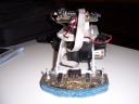
This robot was developed by my colleague and friend Alberto Calvo and me during our studies at University. We got the best possible mark because of the originality and complexity of it.
It’s got 8 Hitec servos (2 per leg) and it could perform some nice sequences of movement which looked really natu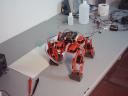 ral. All the control was achieved inside a Xilinx Spartan II FPGA and the code was entirely written in VHDL. The servo controller was a hardware core which accepted a 8bit word for the position and another 8bit word to set the desired speed.
The sequencer and the interface to the PC was implemented inside a PicoBlaze microcontroller synthetized directly into the FPGA. There was no kind of feedback and it just played the stored sequences in its memory but it was quite flexible since we managed to simulate them on the PC.
This is an old project (2003) and due to a data loss I cannot recover any videos or screenshots but I will try to rebuild it someday.
Regards,
Daniel
