Since the very first moment I saw a 2-wheel self-balancing robot I got amazed about all the engineering behind it and I was so excited to build one myself. So now that it’s become a reality let me introduce you to TOBIAS
- Mechanical Description:
-
- 4mm thick PVC sheets
- High torque motors (0.69 Nm)
- High grip wheels (95mm diameter)
- High momentum of inertia (~1.5 kg and modifiable Gravity Center with lead sheets)
- Electronics:
-
- RL-LPC2140 Microcontroller board (LPC2148 32-bit)
- RL-AMC50NP04 H-Bridge MOSFET board
- DC-DC power supply fixed to 10V
- Homemade Inertial Measurement Unit (3-axis accelerometer plus 1-axis gyro)
- Inertial Measurement Unit:
-
- Accelerometer: Slow response & sensitive to acceleration forces due to movement
- Gyroscope: Fast response & integration drift for angle estimation
- Need to mix up the information from both sensors: Kalman Filter
Kalman Filter:
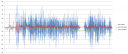 In this graphic you can see some data captured in real time by the microcontroller and then dumped offline to a PC for a later analysis.
The blue signal represents the estimated angle using just the raw data from the accelerometer: arc-tangent of y-axis by x-axis acceleration.
The green signal is the integration of the gyro sensor which clearly shows the drift over the time.
The red signal is the actual angle estimated by the Kalman Filter which shows that in the balancing state the angle falls between -3 and 3 degrees.
Block Diagram:
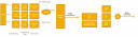 Here you can see the block diagram of the complete system. First, you can observe that the signals are sampled at 3200Hz (oversampling) and then low-pass filtered with a Finite Impulse Response (FIR) Filter with a cutoff frequency of 100Hz.
A 16x decimator is then used to obtain signals with a bandwith of 200Hz and no aliasing. This filtering process improved the angle estimation so much because a lot of noise was removed.
The inputs for the Kalman Filter are the angular rate and the estimated angle from the accelerometer which is computed using an atan2 function call. After that, some tests reported that the angle output by the KF had a precision of about .1º which looks really accurate.
This angle is ready to be processed in order to apply the right torque to the motors using a PID controller -tunned by hand- with more effort than expected (and desired). The integral part of the PID is computed by the trapezoidal rule while the derivative component is calculated using a 7-steps Savitzky-Golay derivator.
The output of the PID is then applied to both motors in order to keep it balanced.
Implementation:
The LPC2148 is a very powerful 32-bit microcontroller which shouldn’t have many problems acting as TOBIAS’ brain. However, the firmware was as optimized as possible in order to allow future improvements and, in the mean time, keep the processor in power down mode while not doing anything to save battery (every mA of current counts ;)).
In order to figure out how the microcontroller could handle all the tasks, a profiling of the execution was performed using a GPIO and a logic analyzer:
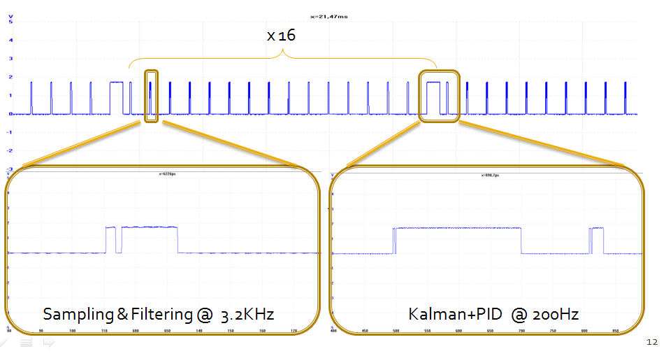
As you can see from the image above, there’s plenty of time for the microcontroller to do some other things. This time was used mainly for logging purposes and in the current version, to read from a IR receiver and controlling TOBIAS using a cheap remote controller from an RC helicopter. This performance was achieved after optimizing the code of the most computationally expensive tasks (Kalman & PID). Also these functions execute from RAM and try to make a good use of the MAM (Memory Accelerator Module) hardware in order to speed its execution up as much as possible.
Considerations for future improvements:
The first approach was building a fairly good balancing robot without spending too much money and now I can say that it was definitely achieved.
The sensors used in the IMU were taken off a cheap PS3 gamepad bought on eBay, there’s no commercial electronic boards (entirely own design) – apart from the cheap step up/down DC-DC controller ($15) -, and both the plastic sheets and wheels are quite cheap and, thus, the overall cost of the robot doesn’t go beyond the 100€ ($140-$150).
However, the cheap motors made all the project a little bit more difficult (and challenging at the same time) than expected: they were not enough responsive and the gearbox wasn’t tight enough allowing you to turn the wheels freely about 3 degrees.
I’m sure that if another motors were used in TOBIAS, the performance would have been way better but it was more exciting to face the PID tunning and the signal processing under these ‘negative’ conditions.
References & Greetings:
T.O.B.B. Balancing Robot by Matthias Toussaint: I would like to thank Matthias so much for answering my e-mails and pointing me in the right direction with his unvaluable advice. All the signal processing was based on TOBB’s and the only main difference is that TOBB uses a very interesting complimentary filter (instead of Kalman) which works incredibly well as you can see in the video posted on his site. Thanks once again Matthias because I learnt a lot from you !!
Also big thanks to my friend Alberto Calvo, the co-author, who also made the 3D artwork shown in the article 😉
Final Result:
All in all, it’s been a very interesting project and, as a reward, TOBIAS won a prize in the Freestyle Robotics Contest at Campus Party ’09 last summer.
In this video you can see TOBIAS in action:
Daniel