Month: February 2019

OVN Routing and ovn-trace

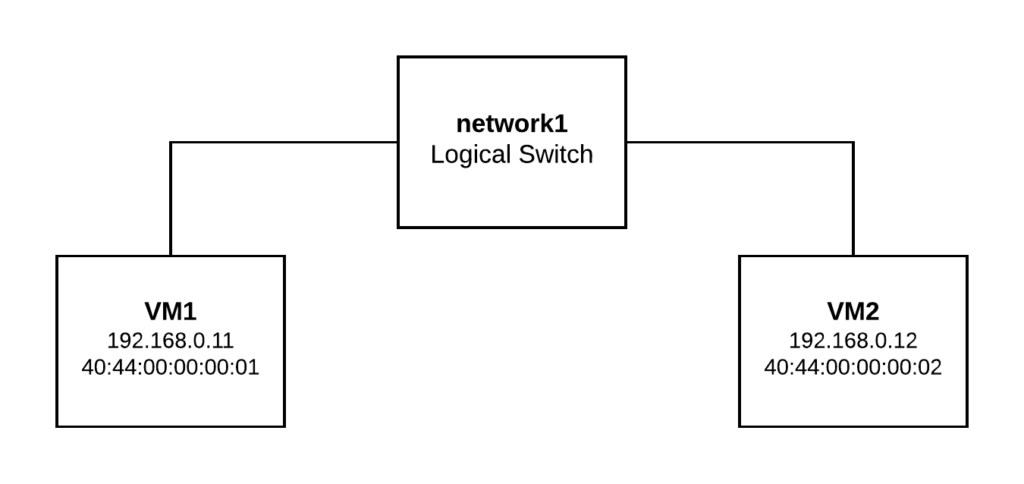
In the last post we covered how OVN distributes the pipeline execution across the different hypervisors thanks to the encapsulation used. Using the same system as a base, let’s create a Logical Router and a second Logical Switch where we can see how routing works between different nodes.


ovn-nbctl ls-add network1
ovn-nbctl ls-add network2
ovn-nbctl lsp-add network1 vm1
ovn-nbctl lsp-add network2 vm2
ovn-nbctl lsp-set-addresses vm1 "40:44:00:00:00:01 192.168.0.11"
ovn-nbctl lsp-set-addresses vm2 "40:44:00:00:00:02 192.168.1.11"

ovn-nbctl lr-add router1
ovn-nbctl lrp-add router1 router1-net1 40:44:00:00:00:03 192.168.0.1/24
ovn-nbctl lsp-add network1 net1-router1
ovn-nbctl lsp-set-addresses net1-router1 40:44:00:00:00:03
ovn-nbctl lsp-set-type net1-router1 router
ovn-nbctl lsp-set-options net1-router1 router-port=router1-net1

ovn-nbctl lrp-add router1 router1-net2 40:44:00:00:00:04 192.168.1.1/24
ovn-nbctl lsp-add network2 net2-router1
ovn-nbctl lsp-set-addresses net2-router1 40:44:00:00:00:04
ovn-nbctl lsp-set-type net2-router1 router
ovn-nbctl lsp-set-options net2-router1 router-port=router1-net2

And then on Worker1 and Worker2 respectively, let’s bind VM1 and VM2 ports inside network namespaces:

# Worker1
ovs-vsctl add-port br-int vm1 -- set Interface vm1 type=internal -- set Interface vm1 external_ids:iface-id=vm1
ip netns add vm1
ip link set vm1 netns vm1
ip netns exec vm1 ip link set vm1 address 40:44:00:00:00:01
ip netns exec vm1 ip addr add 192.168.0.11/24 dev vm1
ip netns exec vm1 ip link set vm1 up
ip netns exec vm1 ip route add default via 192.168.0.1

# Worker2
ovs-vsctl add-port br-int vm2 -- set Interface vm2 type=internal -- set Interface vm2 external_ids:iface-id=vm2
ip netns add vm2
ip link set vm2 netns vm2
ip netns exec vm2 ip link set vm2 address 40:44:00:00:00:02
ip netns exec vm2 ip addr add 192.168.1.11/24 dev vm2
ip netns exec vm2 ip link set vm2 up
ip netns exec vm2 ip route add default via 192.168.1.1

First, let’s check connectivity between two VMs through the Logical Router:

[root@worker1 ~]# ip netns exec vm1 ping 192.168.1.11 -c2
PING 192.168.1.11 (192.168.1.11) 56(84) bytes of data.
64 bytes from 192.168.1.11: icmp_seq=1 ttl=63 time=0.371 ms
64 bytes from 192.168.1.11: icmp_seq=2 ttl=63 time=0.398 ms

--- 192.168.1.11 ping statistics ---
2 packets transmitted, 2 received, 0% packet loss, time 1000ms
rtt min/avg/max/mdev = 0.371/0.384/0.398/0.023 ms

ovn-trace

Let’s now check with ovn-trace how the flow of a packet from VM1 to VM2 looks like and then we’ll verify how this gets realized in our physical deployment with 3 hypervisors: 

[root@central ~]# ovn-trace --summary network1 'inport == "vm1" && eth.src == 40:44:00:00:00:01 && eth.dst == 40:44:00:00:00:03 && ip4.src == 192.168.0.11 && ip4.dst == 192.168.1.11 && ip.ttl == 64'
# ip,reg14=0x1,vlan_tci=0x0000,dl_src=40:44:00:00:00:01,dl_dst=40:44:00:00:00:03,nw_src=192.168.0.11,nw_dst=192.168.1.11,nw_proto=0,nw_tos=0,nw_ecn=0,nw_ttl=64
ingress(dp="network1", inport="vm1") {
    next;
    outport = "net1-router1";
    output;
    egress(dp="network1", inport="vm1", outport="net1-router1") {
        output;
        /* output to "net1-router1", type "patch" */;
        ingress(dp="router1", inport="router1-net1") {
            next;
            ip.ttl--;
            reg0 = ip4.dst;
            reg1 = 192.168.1.1;
            eth.src = 40:44:00:00:00:04;
            outport = "router1-net2";
            flags.loopback = 1;
            next;
            eth.dst = 40:44:00:00:00:02;
            next;
            output;
            egress(dp="router1", inport="router1-net1", outport="router1-net2") {
                output;
                /* output to "router1-net2", type "patch" */;
                ingress(dp="network2", inport="net2-router1") {
                    next;
                    outport = "vm2";
                    output;
                    egress(dp="network2", inport="net2-router1", outport="vm2") {
                        output;
                        /* output to "vm2", type "" */;
                    };
                };
            };
        };
    };
};

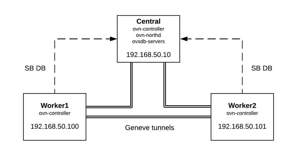
As you can see, the packet goes through 3 OVN datapaths: network1, router1 and network2. As VM1 is on Worker1 and VM2 is on Worker2, the packet will traverse the tunnel between both hypervisors and thanks to the Geneve encapsulation, the execution pipeline will be distributed:

  • Worker1 will execute both ingress and egress pipelines of network1
  • Worker1 will also perform the routing (lines 10 to 28 above) and the ingress pipeline for network2. Then the packet will be pushed to Worker2 via the tunnel.
  • Worker2 will execute the egress pipeline for network2 delivering the packet to VM2.

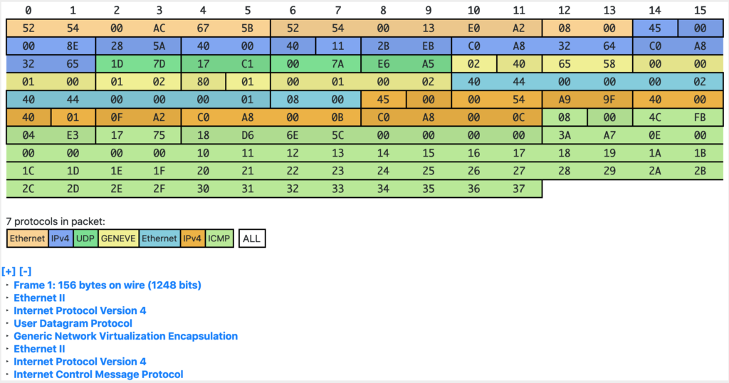
Let’s launch a ping from VM1 and check the Geneve traffic on Worker2: 

52:54:00:13:e0:a2 > 52:54:00:ac:67:5b, ethertype IPv4 (0x0800), length 156: (tos 0x0, ttl 64, id 46587, offset 0, flags [DF], proto UDP (17), length 142)
    192.168.50.100.55145 > 192.168.50.101.6081: [bad udp cksum 0xe6a5 -> 0xb087!] Geneve, Flags [C],
vni 0x8,
proto TEB (0x6558),
options [class Open Virtual Networking (OVN) (0x102)
type 0x80(C) len 8
data 00020001]

From what we learnt in the previous post, when the packet arrives to Worker2, the egress pipeline of Datapath 8 (VNI) will be executed being ingress port = 2 and egress port = 1. Let’s see if it matches what ovn-trace gave us earlier:

egress(dp=”network2″, inport=”net2-router1″, outport=”vm2″) 

[root@central ~]# ovn-sbctl get Datapath_Binding network2 tunnel_key
8
[root@central ~]# ovn-sbctl get Port_Binding net2-router1 tunnel-key
2
[root@central ~]# ovn-sbctl get Port_Binding vm2 tunnel-key
1

What about the reply from VM2 to VM1? If we check the tunnel traffic on Worker2 we’ll see the ICMP echo reply packets with different datapath and ingress/egress ports:

22:19:03.896340 52:54:00:ac:67:5b > 52:54:00:13:e0:a2, ethertype IPv4 (0x0800), length 156: (tos 0x0, ttl 64, id 30538, offset 0, flags [DF], proto UDP (17), length 142)
    192.168.50.101.13530 > 192.168.50.100.6081: [bad udp cksum 0xe6a5 -> 0x5419!] Geneve, Flags [C],
vni 0x7,
proto TEB (0x6558),
options [class Open Virtual Networking (OVN) (0x102)
type 0x80(C) len 8
data 00020001]


[root@central ~]# ovn-sbctl get Datapath_Binding network1 tunnel_key
7
[root@central ~]# ovn-sbctl get Port_Binding net1-router1 tunnel-key
2
[root@central ~]# ovn-sbctl get Port_Binding vm1 tunnel-key
1

As we can see, the routing happens locally in the source node; there’s no need to send the packet to any central/network node as the East/West routing is always distributed with OVN. In the case of North/South traffic, where SNAT is required, traffic will go to the gateway node but we’ll cover this in coming posts.

OpenFlow analysis

Until now, we just focused on the Logical elements but ovn-controller will ultimately translate the Logical Flows into physical flows on the OVN bridge.  Let’s inspect the ports that our bridge has on Worker2:

[root@worker2 ~]# ovs-ofctl show br-int
OFPT_FEATURES_REPLY (xid=0x2): dpid:0000404400000002
n_tables:254, n_buffers:0
capabilities: FLOW_STATS TABLE_STATS PORT_STATS QUEUE_STATS ARP_MATCH_IP
actions: output enqueue set_vlan_vid set_vlan_pcp strip_vlan mod_dl_src mod_dl_dst mod_nw_src mod_nw_dst mod_nw_tos mod_tp_src mod_tp_dst
 1(ovn-centra-0): addr:ea:64:c2:a9:86:fe
     config:     0
     state:      0
     speed: 0 Mbps now, 0 Mbps max
 2(ovn-worker-0): addr:de:96:64:2b:21:4a
     config:     0
     state:      0
     speed: 0 Mbps now, 0 Mbps max
 8(vm2): addr:40:44:00:00:00:02
     config:     0
     state:      0
     speed: 0 Mbps now, 0 Mbps max
 LOCAL(br-int): addr:40:44:00:00:00:02
     config:     PORT_DOWN
     state:      LINK_DOWN
     speed: 0 Mbps now, 0 Mbps max
OFPT_GET_CONFIG_REPLY (xid=0x4): frags=normal miss_send_len=0

We have 3 ports in the OVN bridge:

  1. ovn-centra-0: Tunnel port with Central node
  2. ovn-worker-0: Tunnel port with Worker1
  3. vm2: Our fake virtual machine that we bound to Worker2

When ICMP echo request packets are coming from VM1, we expect them to be arriving via port 2 and being delivered to VM2 on port 8. We can check this by inspecting the flows at table 0 (input) and table 65 (output) for br-int. For a more detailed information of the OpenFlow tables, see ovn-architecture(7) document, section “Architectural Physical Life Cycle of a Packet”.

[root@worker2 ~]# ovs-ofctl dump-flows br-int table=0 | grep idle_age='[0-1],'
cookie=0x0, duration=3845.572s, table=0, n_packets=2979, n_bytes=291942, idle_age=0, priority=100,in_port=2 actions=move:NXM_NX_TUN_ID[0..23]->OXM_OF_METADATA[0..23],move:NXM_NX_TUN_METADATA0[16..30]->NXM_NX_REG14[0..14],move:NXM_NX_TUN_METADATA0[0..15]->NXM_NX_REG15[0..15],resubmit(,33)


[root@worker2 ~]# ovs-ofctl dump-flows br-int table=65 | grep idle_age='[0-1],'
 cookie=0x0, duration=3887.336s, table=65, n_packets=3062, n_bytes=297780, idle_age=0, priority=100,reg15=0x1,metadata=0x8 actions=output:8

I was filtering the dump-flows output to display only those flows with an idle_age of just 0 or 1 seconds. This means that they’ve been recently hit so if we’re inspecting tables with lots of flows, we would filter away unwanted flows to focus just on the ones that we’re really interested. Please, note that for this particular example, I’ve set the VM2 link down to see only incoming ICMP packets from VM1 and hide the replies.

Let’s inspect the input flow on table 0 where the following actions happen:

actions=
move:NXM_NX_TUN_ID[0..23]->OXM_OF_METADATA[0..23],
move:NXM_NX_TUN_METADATA0[16..30]->NXM_NX_REG14[0..14],
move:NXM_NX_TUN_METADATA0[0..15]->NXM_NX_REG15[0..15],
resubmit(,33)

These actions will:

  • Copy the 24 bits of the VNI (Tunnel ID / Logical Datapath) to the OpenFlow metadata.
  • Copy bits 16-30 of the tunnel data (Ingress port) to the OpenvSwitch register 14
  • Copy bits 0-15 of the tunnel data (Egress port) to the OpenvSwitch register 15.

From the ovn-architecture document, we can read:

logical datapath field
A field that denotes the logical datapath through which a
packet is being processed. OVN uses the field that Open‐
Flow 1.1+ simply (and confusingly) calls “metadata” to
store the logical datapath. (This field is passed across
tunnels as part of the tunnel key.)

logical input port field
A field that denotes the logical port from which the
packet entered the logical datapath. OVN stores this in
Open vSwitch extension register number 14.

Geneve and STT tunnels pass this field as part of the
tunnel key. Although VXLAN tunnels do not explicitly
carry a logical input port, OVN only uses VXLAN to commu‐
nicate with gateways that from OVN’s perspective consist
of only a single logical port, so that OVN can set the
logical input port field to this one on ingress to the
OVN logical pipeline.

logical output port field
A field that denotes the logical port from which the
packet will leave the logical datapath. This is initial‐
ized to 0 at the beginning of the logical ingress pipe‐
line. OVN stores this in Open vSwitch extension register
number 15.

Geneve and STT tunnels pass this field as part of the
tunnel key. VXLAN tunnels do not transmit the logical
output port field. Since VXLAN tunnels do not carry a
logical output port field in the tunnel key, when a
packet is received from VXLAN tunnel by an OVN hypervi‐
sor, the packet is resubmitted to table 8 to determine
the output port(s); when the packet reaches table 32,
these packets are resubmitted to table 33 for local de‐
livery by checking a MLF_RCV_FROM_VXLAN flag, which is
set when the packet arrives from a VXLAN tunnel. 

Similarly, we can see that in the output action from table 65, the OpenFlow rule is matching on “reg15=0x1,metadata=0x8” when it outputs the packet to the OpenFlow port number 8 (VM2). As we saw earlier, metadata 8 corresponds to network2 Logical Switch and the output port (reg15) 1 corresponds to the VM2 logical port (tunnel_key 1).


Due to its distributed nature and everything being OpenFlow based, it may be a little bit tricky to trace packets when implementing Software Defined Networking with OVN compared to traditional solutions (iptables, network namespaces, …). Knowing the above concepts and getting familiar with the tools is key to debug OVN systems in an effective way.

OVN – Geneve Encapsulation

In the last post we created a Logical Switch with two ports residing on different hypervisors. Communication between those two ports took place over the tunnel interface using Geneve encapsulation. Let’s now take a closer look at this overlay traffic.

Without diving too much into the packet processing in OVN, we need to know that each Logical Datapath (Logical Switch / Logical Router) has an ingress and an egress pipeline. Whenever a packet comes in, the ingress pipeline is executed and after the output action, the egress pipeline will run to deliver the packet to its destination. More info here: http://docs.openvswitch.org/en/latest/faq/ovn/#ovn

In our scenario, when we ping from VM1 to VM2, the ingress pipeline of each ICMP packet runs on Worker1 (where VM1 is bound to) and the packet is pushed to the tunnel interface to Worker2 (where VM2 resides). When Worker2 receives the packet on its physical interface, the egress pipeline of the Logical Switch (network1) is executed to deliver the packet to VM2. But … How does OVN know where the packet comes from and which Logical Datapath should process it? This is where the metadata in the Geneve headers comes in.

Let’s get back to our setup and ping from VM1 to VM2 and capture traffic on the physical interface (eth1) of Worker2:

[root@worker2 ~]# sudo tcpdump -i eth1 -vvvnnexx

17:02:13.403229 52:54:00:13:e0:a2 > 52:54:00:ac:67:5b, ethertype IPv4 (0x0800), length 156: (tos 0x0, ttl 64, id 63920, offset 0, flags [DF], proto UDP (17), length 142)
    192.168.50.100.7549 > 192.168.50.101.6081: [bad udp cksum 0xe6a5 -> 0x7177!] Geneve, Flags [C], vni 0x1, proto TEB (0x6558), options [class Open Virtual Networking (OVN) (0x102) type 0x80(C) len 8 data 00010002]
        40:44:00:00:00:01 > 40:44:00:00:00:02, ethertype IPv4 (0x0800), length 98: (tos 0x0, ttl 64, id 41968, offset 0, flags [DF], proto ICMP (1), length 84)
    192.168.0.11 > 192.168.0.12: ICMP echo request, id 1251, seq 6897, length 64
        0x0000:  5254 00ac 675b 5254 0013 e0a2 0800 4500
        0x0010:  008e f9b0 4000 4011 5a94 c0a8 3264 c0a8
        0x0020:  3265 1d7d 17c1 007a e6a5 0240 6558 0000
        0x0030:  0100 0102 8001 0001 0002 4044 0000 0002
        0x0040:  4044 0000 0001 0800 4500 0054 a3f0 4000
        0x0050:  4001 1551 c0a8 000b c0a8 000c 0800 c67b
        0x0060:  04e3 1af1 94d9 6e5c 0000 0000 41a7 0e00
        0x0070:  0000 0000 1011 1213 1415 1617 1819 1a1b
        0x0080:  1c1d 1e1f 2021 2223 2425 2627 2829 2a2b
        0x0090:  2c2d 2e2f 3031 3233 3435 3637

17:02:13.403268 52:54:00:ac:67:5b > 52:54:00:13:e0:a2, ethertype IPv4 (0x0800), length 156: (tos 0x0, ttl 64, id 46181, offset 0, flags [DF], proto UDP (17), length 142)
    192.168.50.101.9683 > 192.168.50.100.6081: [bad udp cksum 0xe6a5 -> 0x6921!] Geneve, Flags [C], vni 0x1, proto TEB (0x6558), options [class Open Virtual Networking (OVN) (0x102) type 0x80(C) len 8 data 00020001]
        40:44:00:00:00:02 > 40:44:00:00:00:01, ethertype IPv4 (0x0800), length 98: (tos 0x0, ttl 64, id 16422, offset 0, flags [none], proto ICMP (1), length 84)
    192.168.0.12 > 192.168.0.11: ICMP echo reply, id 1251, seq 6897, length 64
        0x0000:  5254 0013 e0a2 5254 00ac 675b 0800 4500
        0x0010:  008e b465 4000 4011 9fdf c0a8 3265 c0a8
        0x0020:  3264 25d3 17c1 007a e6a5 0240 6558 0000
        0x0030:  0100 0102 8001 0002 0001 4044 0000 0001
        0x0040:  4044 0000 0002 0800 4500 0054 4026 0000
        0x0050:  4001 b91b c0a8 000c c0a8 000b 0000 ce7b
        0x0060:  04e3 1af1 94d9 6e5c 0000 0000 41a7 0e00
        0x0070:  0000 0000 1011 1213 1415 1617 1819 1a1b
        0x0080:  1c1d 1e1f 2021 2223 2425 2627 2829 2a2b
        0x0090:  2c2d 2e2f 3031 3233 3435 3637

Let’s now decode the ICMP request packet (I’m using this tool):

ICMP request inside the Geneve tunnel

Metadata


In the ovn-architecture(7) document, you can check how the Metadata is used in OVN in the Tunnel Encapsulations section. In short, OVN encodes the following information in the Geneve packets:

  • Logical Datapath (switch/router) identifier (24 bits) – Geneve VNI
  • Ingress and Egress port identifiers – Option with class 0x0102 and type 0x80 with 32 bits of data:
         1       15          16
       +---+------------+-----------+
       |rsv|ingress port|egress port|
       +---+------------+-----------+
         0

Back to our example: VNI = 0x000001 and Option Data = 00010002, so from the above:

Logical Datapath = 1   Ingress Port = 1   Egress Port = 2

Let’s take a look at SB database contents to see if they match what we expect:

[root@central ~]# ovn-sbctl get Datapath_Binding network1 tunnel-key
1

[root@central ~]# ovn-sbctl get Port_Binding vm1 tunnel-key
1

[root@central ~]# ovn-sbctl get Port_Binding vm2 tunnel-key
2

We can see that the Logical Datapath belongs to network1, that the ingress port is vm1 and that the output port is vm2 which makes sense as we’re analyzing the ICMP request from VM1 to VM2. 

By the time this packet hits Worker2 hypervisor, OVN has all the information to process the packet on the right pipeline and deliver the port to VM2 without having to run the ingress pipeline again.

What if we don’t use any encapsulation?

This is technically possible in OVN and there’s such scenarios like in the case where we’re managing a physical network directly and won’t use any kind of overlay technology. In this case, our ICMP request packet would’ve been pushed directly to the network and when Worker2 receives the packet, OVN needs to figure out (based on the IP/MAC addresses) which ingress pipeline to execute (twice, as it was also executed by Worker1) before it can go to the egress pipeline and deliver the packet to VM2.

Multinode OVN setup

As a follow up from the last post, we are now going to deploy a 3 nodes OVN setup to demonstrate basic L2 communication across different hypervisors. This is the physical topology and how services are distributed:

  • Central node: ovn-northd and ovsdb-servers (North and Southbound databases) as well as ovn-controller
  • Worker1 / Worker2: ovn-controller connected to Central node Southbound ovsdb-server (TCP port 6642)

In order to deploy the 3 machines, I’m using Vagrant + libvirt and you can checkout the Vagrant files and scripts used from this link. After running ‘vagrant up’, we’ll have 3 nodes with OVS/OVN installed from sources and we should be able to log in to the central node and verify that OVN is up and running and Geneve tunnels have been established to both workers:


[vagrant@central ~]$ sudo ovs-vsctl show
f38658f5-4438-4917-8b51-3bb30146877a
    Bridge br-int
        fail_mode: secure
        Port br-int
            Interface br-int
                type: internal
        Port "ovn-worker-1"
            Interface "ovn-worker-1"
                type: geneve
                options: {csum="true", key=flow, remote_ip="192.168.50.101"}
        Port "ovn-worker-0"
            Interface "ovn-worker-0"
                type: geneve
                options: {csum="true", key=flow, remote_ip="192.168.50.100"}
    ovs_version: "2.11.90"


For demonstration purposes, we’re going to create a Logical Switch (network1) and two Logical Ports (vm1 and vm2). Then we’re going to bind VM1 to Worker1 and VM2 to Worker2. If everything works as expected, we would be able to communicate both Logical Ports through the overlay network formed between both workers nodes.

We can run the following commands on any node to create the logical topology (please, note that if we run them on Worker1 or Worker2, we need to specify the NB database location by running ovn-nbctl with “–db=tcp:192.168.50.10:6641” as 6641 is the default port for NB database):

ovn-nbctl ls-add network1
ovn-nbctl lsp-add network1 vm1
ovn-nbctl lsp-add network1 vm2
ovn-nbctl lsp-set-addresses vm1 "40:44:00:00:00:01 192.168.0.11"
ovn-nbctl lsp-set-addresses vm2 "40:44:00:00:00:02 192.168.0.12"

And now let’s check the Northbound and Southbound databases contents. As we didn’t bind any port to the workers yet, “ovn-sbctl show” command should only list the chassis (or hosts in OVN jargon):

[root@central ~]# ovn-nbctl show
switch a51334e8-f77d-4d85-b01a-e547220eb3ff (network1)
    port vm2
        addresses: ["40:44:00:00:00:02 192.168.0.12"]
    port vm1
        addresses: ["40:44:00:00:00:01 192.168.0.11"]

[root@central ~]# ovn-sbctl show
Chassis "worker2"
    hostname: "worker2"
    Encap geneve
        ip: "192.168.50.101"
        options: {csum="true"}
Chassis central
    hostname: central
    Encap geneve
        ip: "127.0.0.1"
        options: {csum="true"}
Chassis "worker1"
    hostname: "worker1"
    Encap geneve
        ip: "192.168.50.100"
        options: {csum="true"}

Now we’re going to bind VM1 to Worker1:

ovs-vsctl add-port br-int vm1 -- set Interface vm1 type=internal -- set Interface vm1 external_ids:iface-id=vm1
ip netns add vm1
ip link set vm1 netns vm1
ip netns exec vm1 ip link set vm1 address 40:44:00:00:00:01
ip netns exec vm1 ip addr add 192.168.0.11/24 dev vm1
ip netns exec vm1 ip link set vm1 up

And VM2 to Worker2:

ovs-vsctl add-port br-int vm2 -- set Interface vm2 type=internal -- set Interface vm2 external_ids:iface-id=vm2
ip netns add vm2
ip link set vm2 netns vm2
ip netns exec vm2 ip link set vm2 address 40:44:00:00:00:02
ip netns exec vm2 ip addr add 192.168.0.12/24 dev vm2
ip netns exec vm2 ip link set vm2 up

Checking again the Southbound database, we should see the port binding status:

[root@central ~]# ovn-sbctl show
Chassis "worker2"
    hostname: "worker2"
    Encap geneve
        ip: "192.168.50.101"
        options: {csum="true"}
    Port_Binding "vm2"
Chassis central
    hostname: central
    Encap geneve
        ip: "127.0.0.1"
        options: {csum="true"}
Chassis "worker1"
    hostname: "worker1"
    Encap geneve
        ip: "192.168.50.100"
        options: {csum="true"}
    Port_Binding "vm1"

Now let’s check connectivity between VM1 (Worker1) and VM2 (Worker2):

[root@worker1 ~]# ip netns exec vm1 ping 192.168.0.12 -c2
PING 192.168.0.12 (192.168.0.12) 56(84) bytes of data.
64 bytes from 192.168.0.12: icmp_seq=1 ttl=64 time=0.416 ms
64 bytes from 192.168.0.12: icmp_seq=2 ttl=64 time=0.307 ms

--- 192.168.0.12 ping statistics ---
2 packets transmitted, 2 received, 0% packet loss, time 1000ms
rtt min/avg/max/mdev = 0.307/0.361/0.416/0.057 ms


[root@worker2 ~]# ip netns exec vm2 ping 192.168.0.11 -c2
PING 192.168.0.11 (192.168.0.11) 56(84) bytes of data.
64 bytes from 192.168.0.11: icmp_seq=1 ttl=64 time=0.825 ms
64 bytes from 192.168.0.11: icmp_seq=2 ttl=64 time=0.275 ms

--- 192.168.0.11 ping statistics ---
2 packets transmitted, 2 received, 0% packet loss, time 1000ms
rtt min/avg/max/mdev = 0.275/0.550/0.825/0.275 ms

As both ports are located in different hypervisors, OVN is pushing the traffic via the overlay Geneve tunnel from Worker1 to Worker2. In the next post, we’ll analyze the Geneve encapsulation and how OVN uses its metadata internally.

For now, let’s ping from VM1 to VM2 and just capture traffic on the geneve interface on Worker2 to verify that ICMP packets are coming through the tunnel:

[root@worker2 ~]# tcpdump -i genev_sys_6081 -vvnn icmp
tcpdump: listening on genev_sys_6081, link-type EN10MB (Ethernet), capture size 262144 bytes
15:07:42.395318 IP (tos 0x0, ttl 64, id 45147, offset 0, flags [DF], proto ICMP (1), length 84)
    192.168.0.11 > 192.168.0.12: ICMP echo request, id 1251, seq 26, length 64
15:07:42.395383 IP (tos 0x0, ttl 64, id 39282, offset 0, flags [none], proto ICMP (1), length 84)
    192.168.0.12 > 192.168.0.11: ICMP echo reply, id 1251, seq 26, length 64
15:07:43.395221 IP (tos 0x0, ttl 64, id 45612, offset 0, flags [DF], proto ICMP (1), length 84)
    192.168.0.11 > 192.168.0.12: ICMP echo request, id 1251, seq 27, length 64

In coming posts we’ll cover Geneve encapsulation as well as OVN pipelines and L3 connectivity.

Simple OVN setup in 5 minutes

Open Virtual Network (OVN) is an awesome open source project which adds virtual network abstractions to Open vSwitch such as L2 and L3 overlays as well as managing connectivity to physical networks.

OVN has been integrated with OpenStack through networking-ovn which implements a Neutron ML2 driver to realize network resources such as networks, subnets, ports or routers. However, if you don’t want to go through the process of deploying OpenStack, this post provides a quick tutorial to get you started with OVN. (If you feel like it, you can use Packstack to deploy OpenStack RDO which by default will use OVN as the networking backend).

#!/bin/bash

# Disable SELinux
sudo setenforce 0
sudo sed -i 's/^SELINUX=.*/SELINUX=permissive/g' /etc/selinux/config

# Install pre-requisites to compile Open vSwitch
sudo yum group install "Development Tools" -y
sudo yum install python-devel python-six -y

GIT_REPO=${GIT_REPO:-https://github.com/openvswitch/ovs}
GIT_BRANCH=${GIT_BRANCH:-master}

# Clone ovs repo
git clone $GIT_REPO
cd ovs

if [[ "z$GIT_BRANCH" != "z" ]]; then
 git checkout $GIT_BRANCH
fi

# Compile the sources and install OVS
./boot.sh
CFLAGS="-O0 -g" ./configure --prefix=/usr
make -j5 V=0 install
sudo make install

# Start both OVS and OVN services
sudo /usr/share/openvswitch/scripts/ovs-ctl start --system-id="ovn"
sudo /usr/share/openvswitch/scripts/ovn-ctl start_ovsdb --db-nb-create-insecure-remote=yes --db-sb-create-insecure-remote=yes
sudo /usr/share/openvswitch/scripts/ovn-ctl start_northd
sudo /usr/share/openvswitch/scripts/ovn-ctl start_controller

# Configure OVN in OVSDB
sudo ovs-vsctl set open . external-ids:ovn-bridge=br-int
sudo ovs-vsctl set open . external-ids:ovn-remote=unix:/usr/var/run/openvswitch/ovnsb_db.sock
sudo ovs-vsctl set open . external-ids:ovn-encap-ip=127.0.0.1
sudo ovs-vsctl set open . external-ids:ovn-encap-type=geneve

After this, we have a functional OVN system which we can interact with by using the ovn-nbctl tool.

As an example, let’s create a very simple topology consisting on one Logical Switch and attach two Logical Ports to it:

# ovn-nbctl ls-add network1
# ovn-nbctl lsp-add network1 vm1
# ovn-nbctl lsp-add network1 vm2
# ovn-nbctl lsp-set-addresses vm1 "40:44:00:00:00:01 192.168.50.21"
# ovn-nbctl lsp-set-addresses vm2 "40:44:00:00:00:02 192.168.50.22"
# ovn-nbctl show
switch 6f2921aa-e679-462a-ae2b-b581cd958b82 (network1)
port vm2
addresses: ["40:44:00:00:00:02 192.168.50.22"]
port vm1
addresses: ["40:44:00:00:00:01 192.168.50.21"]

What now? Can we communicate vm1 and vm2 somehow?
At this point, we just defined our topology from a logical point of view but those ports are not bound to any hypervisor (Chassis in OVN terminology).

# ovn-sbctl show
Chassis ovn
 hostname: ovnhost
 Encap geneve
 ip: "127.0.0.1"
 options: {csum="true"}

# ovn-nbctl lsp-get-up vm1
down
# ovn-nbctl lsp-get-up vm2
down

For simplicity, let’s bind both ports “vm1” and “vm2” to our chassis simulating that we’re booting two virtual machines. If we would use libvirt or virtualbox to spawn the VMs, their integration with OVS would add the VIF ID to the external_ids:iface-id on the OVN bridge. Check this out for more information.


[root@ovnhost vagrant]# ovs-vsctl add-port br-int vm1 -- set Interface vm1 type=internal -- set Interface vm1 external_ids:iface-id=vm1
[root@ovnhost vagrant]# ovs-vsctl add-port br-int vm2 -- set Interface vm2 type=internal -- set Interface vm2 external_ids:iface-id=vm2
[root@ovnhost vagrant]# ovn-sbctl show
Chassis ovn
hostname: ovnhost
Encap geneve
ip: "127.0.0.1"
options: {csum="true"}
Port_Binding "vm2"
Port_Binding "vm1"
[root@ovnhost vagrant]# ovn-nbctl lsp-get-up vm1
up
[root@ovnhost vagrant]# ovn-nbctl lsp-get-up vm2
up

At this point we have both vm1 and vm2 bound to our chassis. This means that OVN installed the necessary flows in the OVS bridge for them. In order to test this communication, let’s create a namespace for each port and configure a network interface with the assigned IP and MAC addresses:


ip netns add vm1
ip link set vm1 netns vm1
ip netns exec vm1 ip link set vm1 address 40:44:00:00:00:01
ip netns exec vm1 ip addr add 192.168.50.21/24 dev vm1
ip netns exec vm1 ip link set vm1 up

ip netns add vm2
ip link set vm2 netns vm2
ip netns exec vm2 ip link set vm2 address 40:44:00:00:00:02
ip netns exec vm2 ip addr add 192.168.50.22/24 dev vm2
ip netns exec vm2 ip link set vm2 up

After this, we should be able to communicate vm1 and vm2 via the OVN Logical Switch:


[root@ovnhost vagrant]# ip netns list
vm2 (id: 1)
vm1 (id: 0)

[root@ovnhost vagrant]# ip netns exec vm1 ip addr
1: lo: <LOOPBACK> mtu 65536 qdisc noop state DOWN group default qlen 1000
link/loopback 00:00:00:00:00:00 brd 00:00:00:00:00:00
16: vm1: <BROADCAST,MULTICAST,UP,LOWER_UP> mtu 1500 qdisc noqueue state UNKNOWN group default qlen 1000
link/ether 40:44:00:00:00:01 brd ff:ff:ff:ff:ff:ff
inet 192.168.50.21/24 scope global vm1
valid_lft forever preferred_lft forever
inet6 fe80::4244:ff:fe00:1/64 scope link
valid_lft forever preferred_lft forever

[root@ovnhost vagrant]# ip netns exec vm2 ip addr
1: lo: <LOOPBACK> mtu 65536 qdisc noop state DOWN group default qlen 1000
link/loopback 00:00:00:00:00:00 brd 00:00:00:00:00:00
17: vm2: <BROADCAST,MULTICAST,UP,LOWER_UP> mtu 1500 qdisc noqueue state UNKNOWN group default qlen 1000
link/ether 40:44:00:00:00:02 brd ff:ff:ff:ff:ff:ff
inet 192.168.50.22/24 scope global vm2
valid_lft forever preferred_lft forever
inet6 fe80::4244:ff:fe00:2/64 scope link
valid_lft forever preferred_lft forever

[root@ovnhost vagrant]# ip netns exec vm1 ping -c2 192.168.50.22
PING 192.168.50.22 (192.168.50.22) 56(84) bytes of data.
64 bytes from 192.168.50.22: icmp_seq=1 ttl=64 time=0.326 ms
64 bytes from 192.168.50.22: icmp_seq=2 ttl=64 time=0.022 ms

--- 192.168.50.22 ping statistics ---
2 packets transmitted, 2 received, 0% packet loss, time 1000ms
rtt min/avg/max/mdev = 0.022/0.174/0.326/0.152 ms

[root@ovnhost vagrant]# ip netns exec vm2 ping -c2 192.168.50.21
PING 192.168.50.21 (192.168.50.21) 56(84) bytes of data.
64 bytes from 192.168.50.21: icmp_seq=1 ttl=64 time=0.025 ms
64 bytes from 192.168.50.21: icmp_seq=2 ttl=64 time=0.021 ms

--- 192.168.50.21 ping statistics ---
2 packets transmitted, 2 received, 0% packet loss, time 1000ms
rtt min/avg/max/mdev = 0.021/0.023/0.025/0.002 ms

In essence, what this post is describing is the OVN sandbox that comes out of the box with the OVS source code and presented by Russell Bryant . However, the idea behind this tutorial is to serve as a base to setup a simple OVN system as a playground or debugging environment without the burden of deploying OpenStack or any other CMS. In coming articles, we’ll extend the deployment to have more than one node and do more advanced stuff.