Category: Reverse Engineering

Some fun with race conditions and threads in OpenStack

Almost a year ago I reported a bug we were hitting in OpenStack using networking-ovn as a network backend. The symptom was that sometimes Tempest tests were failing in the gate when trying to reach a Floating IP of a VM. The failure rate was not really high so a couple of ‘rechecks’ here and there was enough for us to delay chasing down the bug.

Last week I decided to hunt the bug and attempt to find out the root cause of the failure. Why was the FIP unreachable? For a FIP to be reachable from the external network (Tempest), the following high-level steps should happen:

  1. Tempest needs to ARP query the FIP of the VM
  2. A TCP SYN packet is sent out to the FIP
  3. Routing will happen between external network and internal VM network
  4. The packet will reach the VM and it’ll respond back with a SYN/ACK packet to the originating IP (Tempest executor)
  5. Routing will happen between internal VM network and external network
  6. SYN/ACK packet reaches Tempest executor and the connection will get established on its side
  7. ACK sent to the VM

Some of those steps are clearly failing so time to figure out which.

2018-09-18 17:09:17,276 13788 ERROR [tempest.lib.common.ssh] Failed to establish authenticated ssh connection to cirros@172.24.5.11 after 15 attempts

As first things come first, let’s start off by checking that we get the ARP response of the FIP. We spawn a tcpdump on the external interface where Tempest runs and check traffic to/from 172.24.5.11:

Sep 18 17:09:17.644405 ubuntu-xenial-ovh-bhs1-0002095917 tcpdump[28445]: 17:09:17.275597 1e:d5:ec:49:df:4f > ff:ff:ff:ff:ff:ff, ethertype ARP (0x0806), length 42: Request who-has 172.24.5.11 tell 172.24.5.1, length 28

I can see plenty of those ARP requests but not a single reply. Something’s fishy…

In OVN, ARP queries are responded by ovn-controller so they should hit the gateway node. Let’s inspect the flows there to see if they were installed in OVN Ingress table 1 (which corresponds to OpenFlow table 9):

http://www.openvswitch.org/support/dist-docs/ovn-northd.8.html

Ingress Table 1: IP Input

These flows reply to ARP requests for the virtual IP
addresses configured in the router for DNAT or load bal‐
ancing. For a configured DNAT IP address or a load bal‐
ancer VIP A, for each router port P with Ethernet address
E, a priority-90 flow matches inport == P && arp.op == 1
&& arp.tpa == A (ARP request) with the following actions:

eth.dst = eth.src;
eth.src = E;
arp.op = 2; /* ARP reply. */
arp.tha = arp.sha;
arp.sha = E;
arp.tpa = arp.spa;
arp.spa = A;
outport = P;
flags.loopback = 1;
output;


$ sudo ovs-ofctl dump-flows br-int | grep table=9 | grep "arp_tpa=172.24.5.11"
cookie=0x549ad196, duration=105.055s, table=9, n_packets=0, n_bytes=0, idle_age=105, priority=90,arp,reg14=0x1,metadata=0x87,arp_tpa=172.24.5.11,arp_op=1 actions=move:NXM_OF_ETH_SRC[]->NXM_OF_ETH_DST[],load:0x2->NXM_OF_ARP_OP[],move:NXM_NX_ARP_SHA[]->NXM_NX_ARP_THA[],mod_dl_src:fa:16:3e:3d:bf:46,load:0xfa163e3dbf46->NXM_NX_ARP_SHA[],move:NXM_OF_ARP_SPA[]->NXM_OF_ARP_TPA[],load:0xac18050b->NXM_OF_ARP_SPA[],load:0x1->NXM_NX_REG15[],load:0x1->NXM_NX_REG10[0],resubmit(,32)

So the flow for the ARP responder is installed but it has no hits (note n_packets=0). Looks like for some reason the ARP query is not reaching the router pipeline from the public network. Let’s now take a look at the Logical Router:

This is how the Logical Router looks like:

$ ovn-nbctl show
router 71c37cbd-4aa9-445d-a9d1-cb54ee1d3207 (neutron-cc163b42-1fdf-4cfa-a2ff-50c521f04222) (aka tempest-TestSecurityGroupsBasicOps-router-1912572360)
     port lrp-2a1bbf89-adee-4e74-b65e-1ac7a1ba4089
         mac: "fa:16:3e:3d:bf:46"
         networks: ["10.1.0.1/28"]
     nat 2eaaa99e-3be8-49ad-b801-ad198a6084fd
         external ip: "172.24.5.7"
         logical ip: "10.1.0.0/28"
         type: "snat"
     nat 582bab87-8acb-4905-8723-948651811193
         external ip: "172.24.5.11"
         logical ip: "10.1.0.6"
         type: "dnat_and_snat"

We can see that we have two NAT entries: one for the FIP (172.24.5.11 <-> 10.1.0.6) and one SNAT entry for the gateway which should allow the VM to access the external network.

There’s also one router port which connects the VM subnet to the router but… wait …There’s no gateway port connected to the router!! This means that the FIP is unreachable so at this point we know what’s going on but… WHY? We need to figure out why the gateway port is not added. Time to check the code and logs:

Code wise (see below), the gateway is added upon router creation. It’ll imply creating a router (L9), the gateway port (L26) and adding it to the Logical Switch as you can see here. Afterwards, it’ll add a static route with the next hop to the router (L37). Also, you can see that everything is inside a context manager (L8) where a transaction with OVSDB is created so all the commands are expected to be commited/failed as a whole:

def create_router(self, router, add_external_gateway=True):
    """Create a logical router."""
    context = n_context.get_admin_context()
    external_ids = self._gen_router_ext_ids(router)
    enabled = router.get('admin_state_up')
    lrouter_name = utils.ovn_name(router['id'])
    added_gw_port = None
    with self._nb_idl.transaction(check_error=True) as txn:
        txn.add(self._nb_idl.create_lrouter(lrouter_name,
                                            external_ids=external_ids,
                                            enabled=enabled,
                                            options={}))
        if add_external_gateway:
            networks = self._get_v4_network_of_all_router_ports(
                context, router['id'])
            if router.get(l3.EXTERNAL_GW_INFO) and networks is not None:
                added_gw_port = self._add_router_ext_gw(context, router,
                                                        networks, txn)

def _add_router_ext_gw(self, context, router, networks, txn):
    router_id = router['id']
    # 1. Add the external gateway router port.
    gw_info = self._get_gw_info(context, router)
    gw_port_id = router['gw_port_id']
    port = self._plugin.get_port(context, gw_port_id)
    self._create_lrouter_port(router_id, port, txn=txn)

    columns = {}
    if self._nb_idl.is_col_present('Logical_Router_Static_Route',
                                   'external_ids'):
        columns['external_ids'] = {
            ovn_const.OVN_ROUTER_IS_EXT_GW: 'true',
            ovn_const.OVN_SUBNET_EXT_ID_KEY: gw_info.subnet_id}

    # 2. Add default route with nexthop as gateway ip
    lrouter_name = utils.ovn_name(router_id)
    txn.add(self._nb_idl.add_static_route(
        lrouter_name, ip_prefix='0.0.0.0/0', nexthop=gw_info.gateway_ip,
        **columns))

    # 3. Add snat rules for tenant networks in lrouter if snat is enabled
    if utils.is_snat_enabled(router) and networks:
        self.update_nat_rules(router, networks, enable_snat=True, txn=txn)
    return port

So, how is it possible that the Logical Router exists while the gateway port does not if everything is under the same transaction? We’re nailing this down and now we need to figure that out by inspecting the transactions in neutron-server logs:

DEBUG ovsdbapp.backend.ovs_idl.transaction [-] Running txn n=1 command(idx=2): AddLRouterCommand(may_exist=True, columns={'external_ids': {'neutron:gw_port_id': u'8dc49792-b37a-48be-926a-af2c76e269a9', 'neutron:router_name': u'tempest-TestSecurityGroupsBasicOps-router-1912572360', 'neutron:revision_number': '2'}, 'enabled': True, 'options': {}}, name=neutron-cc163b42-1fdf-4cfa-a2ff-50c521f04222) {{(pid=32314) do_commit /usr/local/lib/python2.7/dist-packages/ovsdbapp/backend/ovs_idl/transaction.py:84}}

The above trace is written when the Logical Router gets created but surprisingly we can see idx=2 meaning that it’s not the first command of a transaction. But… How is this possible? We saw in the code that it was the first command to be executed when creating a router and this is the expected sequence:

  1. AddLRouterCommand
  2. AddLRouterPortCommand
  3. SetLRouterPortInLSwitchPortCommand
  4. AddStaticRouteCommand

Let’s check the other commands in this transaction in the log file:

DEBUG ovsdbapp.backend.ovs_idl.transaction [-] Running txn n=1 command(idx=0): AddLRouterPortCommand(name=lrp-1763c78f-5d0d-41d4-acc7-dda1882b79bd, may_exist=True, lrouter=neutron-d1d3b2f2-42cb-4a86-ac5a-77001da8fee2, columns={'mac': u'fa:16:3e:e7:63:b9', 'external_ids': {'neutron:subnet_ids': u'97d41327-4ea6-4fff-859c-9884f6d1632d', 'neutron:revision_number': '3', 'neutron:router_name': u'd1d3b2f2-42cb-4a86-ac5a-77001da8fee2'}, 'networks': [u'10.1.0.1/28']}) {{(pid=32314) do_commit /usr/local/lib/python2.7/dist-packages/ovsdbapp/backend/ovs_idl/transaction.py:84}}

DEBUG ovsdbapp.backend.ovs_idl.transaction [-] Running txn n=1 command(idx=1): SetLRouterPortInLSwitchPortCommand(if_exists=True, lswitch_port=1763c78f-5d0d-41d4-acc7-dda1882b79bd, lrouter_port=lrp-1763c78f-5d0d-41d4-acc7-dda1882b79bd, is_gw_port=False, lsp_address=router) {{(pid=32314) do_commit /usr/local/lib/python2.7/dist-packages/ovsdbapp/backend/ovs_idl/transaction.py:84}}

DEBUG ovsdbapp.backend.ovs_idl.transaction [-] Running txn n=1 command(idx=2): AddLRouterCommand(may_exist=True, columns={'external_ids': {'neutron:gw_port_id': u'8dc49792-b37a-48be-926a-af2c76e269a9', 'neutron:router_name': u'tempest-TestSecurityGroupsBasicOps-router-1912572360', 'neutron:revision_number': '2'}, 'enabled': True, 'options': {}}, name=neutron-cc163b42-1fdf-4cfa-a2ff-50c521f04222)

DEBUG ovsdbapp.backend.ovs_idl.transaction [-] Running txn n=1 command(idx=3): AddNATRuleInLRouterCommand(lrouter=neutron-d1d3b2f2-42cb-4a86-ac5a-77001da8fee2, columns={'external_ip': u'172.24.5.26', 'type': 'snat', 'logical_ip': '10.1.0.0/28'}) {{(pid=32314) do_commit /usr/local/lib/python2.7/dist-packages/ovsdbapp/backend/ovs_idl/transaction.py:84}}

It looks like this:

  1. AddLRouterPortCommand
  2. SetLRouterPortInLSwitchPortCommand
  3. AddLRouterCommand (our faulty router)
  4. AddNATRuleInLRouterCommand

Definitely, number 3 is our command that got in between a totally different transaction from a totally different test being executed concurrently in the gate . Most likely, according to the commands 1, 2 and 4 it’s another test adding a new interface to a different router here. It’ll create a logical router port, add it to the switch and update the SNAT rules. All those debug traces come from the same process ID so the transactions are getting messed up from the two concurrent threads attempting to write into OVSDB.

This is the code that will create a new transaction object in ovsdbapp or, if it was already created, will return the same object. The problem here comes when two different threads/greenthreads attempt to create their own separate transactions concurrently:

    @contextlib.contextmanager
    def transaction(self, check_error=False, log_errors=True, **kwargs):
        """Create a transaction context.

        :param check_error: Allow the transaction to raise an exception?
        :type check_error:  bool
        :param log_errors:  Log an error if the transaction fails?
        :type log_errors:   bool
        :returns: Either a new transaction or an existing one.
        :rtype: :class:`Transaction`
        """
        if self._nested_txn:
            yield self._nested_txn
        else:
            with self.create_transaction(
                    check_error, log_errors, **kwargs) as txn:
                self._nested_txn = txn
                try:
                    yield txn
                finally:
                    self._nested_txn = None
  1. Test1 will open a new transaction and append  AddLRouterPortCommand and SetLRouterPortInLSwitchPortCommand commands to it.
  2. Test1 will now yield its execution (due to some I/O in the case of greenthreads as eventlet is heavily used in OpenStack).
  3. Test 2 (our failing test!) will attempt to create its own transaction.
  4. As everything happens in the same process, self._nested_txn was previously assigned due to step number 1 and is returned here.
  5. Test 2 will append the  AddLRouterCommand command to it.
  6. At this point Test 2 will also yield its execution. Mainly due to the many debug traces that we have for scheduling a gateway port on the available chassis in OVN so this is one of the most likely parts of the code for the race condition to occur.
  7. Test 1 will append the rest of the commands and commit the transaction to OVSDB.
  8. OVSDB will execute the commands and close the transaction.
  9. When Test 2 appends the rest of its commands, the transaction is closed and will never get commited, ie. only AddLRouterCommand was applied to the DB leaving the gateway port behind in OVN.

The nested transaction mechanism in ovsdbapp was not taking into account that two different threads attempt to open separate transactions so we needed to patch this to make it thread safe. The solution that we came up with was to create a different transaction per thread ID and add the necessary coverage to the unit tests.

Two more questions arise at this point:

  • Why this is not happening in Neutron if they also use ovsdbapp there?

Perhaps it’s happening but they don’t make that much use of multiple commands transactions. Instead, most of the time it’s single command transactions that are less prone to this particular race condition.

  • Why does it happen mostly when creating a gateway port?

Failing to create a gateway port leads to VMs to lose external connectivity so the failure is very obvious. There might be other conditions where this bug happens and we’re not even realizing, producing weird behaviors. However, it’s true that this particular code which creates the gateway port is complex as it implies scheduling the port into the least loaded available chassis so a number of DEBUG traces were added. As commented through the blog post, writing these traces will result in yielding the execution to a different greenthread where the disaster occurs!

This blog post tries to show a top-bottom approach to debugging failures that are not easily reproducible. It requires a solid understanding of the system architecture (OpenStack components, OVN, databases) and its underlying technologies (Python, greenthreads) to be able to tackle this kind of race conditions in an effective way.
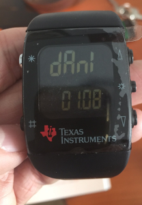
RFCat, TI Chronos and replaying RF signals :)

After my first contact with the RTL-SDR a couple of days ago , I’ve been researching a bit more and found this fantastic blog post by Adam Laurie which describes how to use a TI Chronos development kit to send arbitrary sub-1GHz signals. It happens that I had such a kit so I decided to emulate another garage door opener, but this time using RFCat.

Loading RFCat firmware into the Chronos USB Dongle

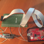
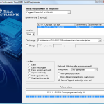
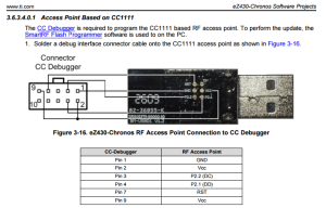
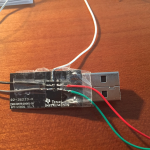
First thing I did was to flash the USB dongle with the RFCat firmware so that I could emulate the remote from a python script. As I had a CC Programmer handy (you can also use GoodFET), I wired it up by following the diagram below and flashed the RFCat bin for the ez Chronos dongle using the SmartRF Flash Programmer tool.

ez_jtag_diagram


ez_jtag

ez_rfcat

ez_hack2

You can either flash the dongle with the RFCat binary itself or with the CC Bootloader which will allow you to update the dongle further without having to use the JTAG. I took the second approach so after flashing the bootloader, you’ll need to flash the actual RFCat firmware:

python bootloader.py /dev/ttyACM0 download RfCatChronosCCBootloader-150225.hex

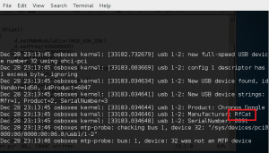
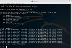
After successfully flashing the dongle, it should show up as “RFCat” and you should be able to communicate with it from the rfcat interpreter:

RFCat_enumRFCat_r

As the communication with the dongle was good, it was time to analyze the signal sent by the remote and write some code to replay it using RFCat.

Signal Analysis

For the analysis part, I used the SDR# tool for Windows: tuned the right frequency (433.92MHz) and saved the signal into a Wav file for later analysis with Audacity.

audacity_ref1_mod

It’s a fixed code and looks pretty straightforward: short and long pulses. We can estimate the length of each type by measuring the number of samples. In this case, short pulses took 3000 samples or 1200us (sample rate was 2.4Ms on SDRSharp).

A good way to represent the signal is to encode the “long pulse plus silence” as “1” and the “short pulse plus silence” as “0”. Then, the frame would look like this:

1  0  1  1  0  1  1  1  1  1  1  0  0  0  0  0  1  0  1  1  0  0  1  1  0  0  1  1  0  0  1  1  1

As the “1” is formed by two high and one low short pulses of equal duration, we can express it as “110”. Similarly, our “0” can be represented as “100” and the frame now would be:

110 100 110 110 100 110 110 110 110 110 110 100 100 100 100 100
110 100 110 110 100 100 110 110 100 100 110 110 100 100 110 110 110

However, if we zoom in on the signal, we can see that the pulses are divided in more little pulses that we’ll need to encode in some way:

audacity_ref2

So, the final frame would make us rewrite the previous one changing every “1” bit by \xAA\xAA  and every “0” bit by \x00\x00 to maintain the length of each bit (see code below).  The duration of each bit is now about 80 us.

Replaying signal with RFCat

Now that we have analyzed the signal, it’s time to write a Python script to interface the RFCat dongle so that it generates the frames accordingly. Afterwards, we’ll capture the signal back to make sure that both the waveform and timing are correct:

from rflib import*
from time import sleep

pkt = '\xAA\xAA\xAA\xAA\x00\x00\xAA\xAA\x00\x00\x00\x00\xAA\xAA\xAA\xAA\x00\x00\xAA\xAA\xAA\xAA\x00\x00\xAA\xAA\x00\x00\x00\x00\xAA\xAA\xAA\xAA\x00\x00\xAA\xAA\xAA\xAA\x00\x00\xAA\xAA\xAA\xAA\x00\x00\xAA\xAA\xAA\xAA\x00\x00\xAA\xAA\xAA\xAA\x00\x00\xAA\xAA\xAA\xAA\x00\x00\xAA\xAA\x00\x00\x00\x00\xAA\xAA\x00\x00\x00\x00\xAA\xAA\x00\x00\x00\x00\xAA\xAA\x00\x00\x00\x00\xAA\xAA\x00\x00\x00\x00\xAA\xAA\xAA\xAA\x00\x00\xAA\xAA\x00\x00\x00\x00\xAA\xAA\xAA\xAA\x00\x00\xAA\xAA\xAA\xAA\x00\x00\xAA\xAA\x00\x00\x00\x00\xAA\xAA\x00\x00\x00\x00\xAA\xAA\xAA\xAA\x00\x00\xAA\xAA\xAA\xAA\x00\x00\xAA\xAA\x00\x00\x00\x00\xAA\xAA\x00\x00\x00\x00\xAA\xAA\xAA\xAA\x00\x00\xAA\xAA\xAA\xAA\x00\x00\xAA\xAA\x00\x00\x00\x00\xAA\xAA\x00\x00\x00\x00\xAA\xAA\xAA\xAA\x00\x00\xAA\xAA\xAA\xAA\x00\x00\xAA\xAA\xAA\xAA\x00\x00'

NUM_REPS	= 10		# times the frame will be sent
DELAY 		= 0.02	# seconds between frames

try:

	d = RfCat()
	d.setMdmModulation(MOD_ASK_OOK)
	d.setFreq(433290000)	# Set freq to 433.92MHz
	d.setMaxPower()
	d.setMdmSyncMode(0)		# Don't send preamble/sync word
	d.setMdmDRate((int)(1.0/0.000080))	# Our bits are 80us long
 	d.makePktFLEN(len(pkt))

	print "Sending frames "
	for i in range(0,NUM_REPS):
		sys.stdout.write(".")
		d.RFxmit(pkt)
		sleep(DELAY)
	print " Done\n"
	d.setModeIDLE()

except Exception, e:
	sys.exit("Error %s" % str(e))

Now let’s run the script and capture the signal back with SDR# to check if it looks like it should:

audacity_ref_captured1_mod

audacity_captured_zoom1

The first picture shows both our reference signal (sent by the remote) and the one generated with the RFCat dongle. The second picture shows the detail of each bit. As expected, it opened the door although the output power seemed a bit too low . Maybe there’s a hack to improve the antenna of the Chronos dongle?  🙂

Replaying the signal with the Chronos Sports Watch

Okay, the hard part is over so let’s have some fun and replay the signal directly from our wrist 🙂

The ChronIC project is pretty much like the RFCat firmware but can loaded directly into the Chronos Sports Watch so that pre-loaded signals can be sent just by pressing the up/down buttons. I modified the code to make the watch send our frame every time I pressed the UP button. Below is the code that will do the magic, and a couple of useful Python functions (from Adam’s code) to calculate the register values for your bitrate and frequency:


 def setfreq(freq):
	mhz= 26
	freqmult = (0x10000 / 1000000.0) / mhz
	num = int(freq * freqmult)
	freq0= num & 0xff
	payload= chr(freq0)
	freq1= (num >> 8) & 0xff
	payload += chr(freq1)
	freq2= (num >> 16) & 0xff
	payload += chr(freq2)
	print '- FREQ2: %02x FREQ1: %02x FREQ0: %02x -' % (freq2, freq1, freq0)

def setdatarate(drate):
	mhz= 26
	drate_e = None
	drate_m = None
	for e in range(16):
		m = int((drate * pow(2,28) / (pow(2,e)* (mhz*1000000.0))-256) + .5)        # rounded evenly
		if m < 256:
			drate_e = e
			drate_m = m
			break
	if drate_e is None:
		return False, None
	drate = 1000000.0 * mhz * (256+drate_m) * pow(2,drate_e) / pow(2,28)
	print 'drate_e: %02x  drate_m: %02x' %(drate_e,drate_m)
void config_garage(u8 line)
{
	// gap between data pulses
	//Button_Delay= 0;
	Button_Delay= 20;
	// how many times to send per button press
	Button_Repeat= 10;

	// set button content

	Up_Buttons= 1;
	// packet length
	Button_Up_Data[0][0]= 198;
	// payload
	memcpy(&Button_Up_Data[0][1],"\xAA,\xAA,\xAA,\xAA,\x00,\x00,\xAA,\xAA,\
 \x00,\x00,\x00,\x00,\xAA,\xAA,\xAA,\xAA,\x00,\x00,\xAA,\xAA,\xAA,\xAA,\x00,\x00,\
 \xAA,\xAA,\x00,\x00,\x00,\x00,\xAA,\xAA,\xAA,\xAA,\x00,\x00,\xAA,\xAA,\xAA,\xAA,\
 \x00,\x00,\xAA,\xAA,\xAA,\xAA,\x00,\x00,\xAA,\xAA,\xAA,\xAA,\x00,\x00,\xAA,\xAA,\
 \xAA,\xAA,\x00,\x00,\xAA,\xAA,\xAA,\xAA,\x00,\x00,\xAA,\xAA,\x00,\x00,\x00,\x00,\
 \xAA,\xAA,\x00,\x00,\x00,\x00,\xAA,\xAA,\x00,\x00,\x00,\x00,\xAA,\xAA,\x00,\x00,\
 \x00,\x00,\xAA,\xAA,\x00,\x00,\x00,\x00,\xAA,\xAA,\xAA,\xAA,\x00,\x00,\xAA,\xAA,\
 \x00,\x00,\x00,\x00,\xAA,\xAA,\xAA,\xAA,\x00,\x00,\xAA,\xAA,\xAA,\xAA,\x00,\x00,\
 \xAA,\xAA,\x00,\x00,\x00,\x00,\xAA,\xAA,\x00,\x00,\x00,\x00,\xAA,\xAA,\xAA,\xAA,\
 \x00,\x00,\xAA,\xAA,\xAA,\xAA,\x00,\x00,\xAA,\xAA,\x00,\x00,\x00,\x00,\xAA,\xAA,\
 \x00,\x00,\x00,\x00,\xAA,\xAA,\xAA,\xAA,\x00,\x00,\xAA,\xAA,\xAA,\xAA,\x00,\x00,\
 \xAA,\xAA,\x00,\x00,\x00,\x00,\xAA,\xAA,\x00,\x00,\x00,\x00,\xAA,\xAA,\xAA,\xAA,\
 \x00,\x00,\xAA,\xAA,\xAA,\xAA,\x00,\x00,\xAA,\xAA,\xAA,\xAA,\x00,\x00",Button_Up_Data[0][0]);

	Down_Buttons= 0;

	// set frequency (433920000)
	ChronicRF.freq0= 0x71;
	ChronicRF.freq1= 0xB0;
	ChronicRF.freq2= 0x10;

	// set data rate (pulsewidth 80us)
	// drate_m
	ChronicRF.mdmcfg3= 0xf8;
	// drate_e
	ChronicRF.mdmcfg4 &= 0xf0;
	ChronicRF.mdmcfg4 |= 8;

	// set modulation
	ChronicRF.mdmcfg2 &= ~MASK_MOD_FORMAT;
	ChronicRF.mdmcfg2 |= MOD_OOK;
	// set sync mode
	ChronicRF.mdmcfg2 &= ~MASK_SYNC_MODE;
	ChronicRF.mdmcfg2 |= SYNC_MODE_NONE;
	// set manchester false
	ChronicRF.mdmcfg2 &= ~MASK_MANCHESTER;
	display_symbol(LCD_ICON_RECORD, SEG_ON);
	Emulation_Mode= EMULATION_MODE_GARAGE;
}

After  building the code with Code Composer and loading it into the Watch with the JTAG included in the kit, a new menu is available and the signal’s going to be sent every time we press the UP button.

ez_menu

🙂 🙂

All the information in this blog is for educational  purposes only.  You shall not misuse the information to gain unauthorized access.

Hello RTL-SDR

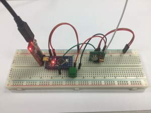
A new cool gadget has fallen into my hands: a SDR DVB-T dongle based on the Realtek RTL2832U chipset. Little did I know I was gonna get so fascinated about this world and first thing I wanted to try is to open my garage door from an Arduino as a “Hello World” exercise.

remote

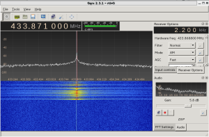
Firstly, I installed the necessary software on a Kali Linux distribution and checked the frequency of the remote with the gqrx tool:

GQRX

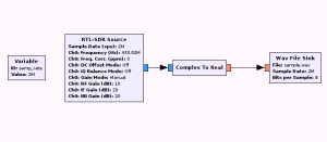
Then, I dumped the signal for further analysis into a wav file using the gnuradio-companion software:

gnuradio-companion

This flowgraph will let us sample the signal sent by the remote and write it into a Wav file. After pressing the buttons on the remote we can see how it looks like in Audacity:

The modulation used by the remote is OOK and looks like it uses Manchester codification. Using the rtl_433 tool, I was able to decode the frame and correlate it with the waveform above:

*** signal_start = 2189802, signal_end = 2300238
signal_len = 110436,  pulses = 86
Iteration 1. t: 404    min: 110 (47)    max: 699 (39)    delta 241
Iteration 2. t: 404    min: 110 (47)    max: 699 (39)    delta 0
Pulse coding: Short pulse length 110 - Long pulse length 699

Short distance: 83, long distance: 675, packet distance: 4804

p_limit: 404
bitbuffer:: Number of rows: 6 
[00] {4} f0 : 1111
[01] {18} 23 23 c0 : 00100011 00100011 11
[02] {18} 23 23 c0 : 00100011 00100011 11
[03] {18} 23 23 c0 : 00100011 00100011 11
[04] {18} 23 23 c0 : 00100011 00100011 11
[05] {10} 23 00 : 00100011 00

As long as the button’s pressed, the remote will keep on transmitting the 18-bit frame which we have identified as:   00100011 00100011 11. This bitstream can be clearly seen on Audacity.

From the output above, the short pulses got 110 counts and the long pulses 699. Since the rtl_433 tool samples at 250KHz, it means that they last 440us while the long ones last 2800us. All we need to do now is write the software for the Arduino board to replicate the signal:

#define rfTransmitPin 4
#define ledPin 13
#define buttonPin 9      

void setup(){

	pinMode(rfTransmitPin, OUTPUT);
	pinMode(ledPin, OUTPUT);
	pinMode(botonPin, INPUT);       

	digitalWrite(rfTransmitPin, LOW);
 }

  void loop(){
    if(digitalRead(buttonPin) == HIGH)   // if the button is pressed, tx the code
      transmitCode();
  }

#define SHORT_WAIT	delayMicroseconds(440)
#define LONG_WAIT	delayMicroseconds(2800)
#define TX_LOW		digitalWrite(rfTransmitPin, LOW)
#define TX_HIGH		digitalWrite(rfTransmitPin, HIGH)
#define OUTPUT_0	{TX_HIGH; SHORT_WAIT; TX_LOW; LONG_WAIT;}
#define OUTPUT_1	{TX_HIGH; LONG_WAIT;  TX_LOW; SHORT_WAIT;}

#define FRAME_SIZE        18

unsigned char code[] = {0,0,1,0,0,0,1,1,0,0,1,0,0,0,1,1,1,1};

void transmitCode() {

    digitalWrite(ledPin, HIGH);

	for(int i=0;i<CODE_SIZE;i++)
	{
		if(code_left[i] == 1)
		{
			OUTPUT_1;
		}
		else
		{
			OUTPUT_0;
		}
	}
	digitalWrite(rfTransmitPin, LOW);
	delay(200);

    digitalWrite(ledPin, LOW);
 }
 

Now, let’s download it into the microcontroller and capture what it’s sent to see if it matches the original code:

Arduino Sample


The waveform looks pretty much the same as the one sent by the remote. Also, the rtl_433 tool is able to decode it properly and the timing looks quite nice too:

*** signal_start = 12434285, signal_end = 12748315
signal_len = 314030,  pulses = 144
Iteration 1. t: 413    min: 115 (84)    max: 711 (60)    delta 8
Iteration 2. t: 413    min: 115 (84)    max: 711 (60)    delta 0
Pulse coding: Short pulse length 115 - Long pulse length 711
Short distance: 112, long distance: 708, packet distance: 25527

p_limit: 413
bitbuffer:: Number of rows: 8
[00] {18} 23 23 c0 : 00100011 00100011 11
[01] {18} 23 23 c0 : 00100011 00100011 11
[02] {18} 23 23 c0 : 00100011 00100011 11
[03] {18} 23 23 c0 : 00100011 00100011 11
[04] {18} 23 23 c0 : 00100011 00100011 11
[05] {18} 23 23 c0 : 00100011 00100011 11
[06] {18} 23 23 c0 : 00100011 00100011 11
[07] {18} 23 23 c0 : 00100011 00100011 11

Now we’re sure that the Arduino board will transmit the same signal, it’s time to try it by the garage door and… it WORKS! 🙂

It is a very simple project but as a first contact with the RTL-SDR world I had a lot of fun. I’m looking forward to learning more about it, especially the gnuradio-companion software for signal processing and analysis.


Creating library signatures for IDA

I’ll briefly explain how to generate the signature file for a given library in order to import it from IDA Pro and get the library functions identified by the disassembler (which can save you hours from digging into ‘well-known’ functions).

Requirements: FLAIR tools installed.

Execute the COFF parser

> pcf ms32.lib miracl

ms32.lib: skipped 0, total 432

>sigmake miracl miracl

You might get collision errors here:

See the documentation to learn how to resolve collisitions.
: modules/leaves: 9021136/432, COLLISIONS: 382

At this point, just edit the .exc file, remove the comments in the first lines and re-execute the sigmake command.

Now you’ll see a miracl.sig ready to be imported from the FLIRT signatures window in IDA Pro.

Daniel Álvarez

Debugging Windows Mobile 6 Applications with IDA

Today I’ve been trying to debug an application remotely with IDA Pro and I found the following error when launched the program:

Copying the debugger server to PocketPC ...
Could not invoke debugger server at PocketPC: Access denied.

Thus, surfing the web I found a workaround regarding the security polices of the handheld. Just by changing some values in the registry you will be able to copy/invoke the debugger remotely.

Key: 'HKLMSecurityPoliciesPolicies001001'  from  value DWORD:2 to value DWORD:1

Key: 'HKLMSecurityPoliciesPolicies00100b' change  to value DWORD:1

And now you’ll be able to debug your programs remotely 🙂

Cheers,

Daniel

Crackme 4 – Linux Crackme

In this article I will explain how I solved lagalopex crackme from crackmes.de.You can download my keygen and its source code from here.

These are the rules and information:

Get a working keygen.
Allowed are only GPLed-tools.
Patching/Hijacking prohibited ;)

Difficulty: 3 – Getting harder
Platform: Unix/linux etc.
Language: C/C++

Ok, first let’s execute it to see what’s going on and if we are prompted for something:

daniel@gargamel:~/crackme/lagalopex$ ./cm3
Your name: daniel
Hello daniel, lets see what you've done so far...
daniel@gargamel:~/crackme/lagalopex$

Ok, we have done nothing so far so we cannot expect anything else. If we test the binary with the ‘file’ command we will see that it is not stripped so we might get some useful information from its ‘nm’ and ‘strings’ output:

daniel@gargamel:~/crackme/lagalopex$ nm cm3
0804bf58 T gcd1
0804bf92 T gcd2
0804bfcc T gcd3
0804bea6 T gcd_
U getline@@GLIBC_2.0
U getppid@@GLIBC_2.0
U getpwuid@@GLIBC_2.0
U getsid@@GLIBC_2.0
U getuid@@GLIBC_2.0
0804c007 T gs
0804c0ee T main
U memcpy@@GLIBC_2.0
U open@@GLIBC_2.0
U printf@@GLIBC_2.0
U pthread_attr_destroy@@GLIBC_2.0
U pthread_attr_init@@GLIBC_2.1
U pthread_attr_setdetachstate@@GLIBC_2.0
U pthread_create@@GLIBC_2.1
U pthread_exit@@GLIBC_2.0
U pthread_join@@GLIBC_2.0
U puts@@GLIBC_2.0
0804c03d T rad
0804bf04 T rad_
0804c086 T calc
0804bc34 t rmd160_final
0804be4a T rmd160_hash_buffer
080488b4 t rmd160_init
080488fe t rmd160_trans
0804bb15 t rmd160_write

daniel@gargamel:~/crackme/lagalopex$ strings cm3
[...]
Get a name first...
Hello %s, lets see what you've done so far...
%s/.key_%s
%s/.key_%s_%i
Nice, you got it!

I didn’t list all of them but the interesting ones. We can see that there are threads involved which will probably make our reversing job harder. Also, we can see the presumably goodboy string: ‘Nice, you got it’ and some print format strings. I will not go much in detail with the reversing process and I will just show a flow diagram:

flowchart-2

As you can see in the flow diagram, it first computes a hash value of 20 bytes (RIPEMD-160) and then iterates over it through some calculations performed by 6 threads (hence, a total of 120 threads are created). I will describe briefly what these threads do:

  • gcd1
0804bf58 gcd1:
 804bf58:	55                   	push   ebp
 804bf59:	89 e5                	mov    ebp,esp
 804bf5b:	83 ec 08             	sub    esp,0x8
 804bf5e:	8b 45 08             	mov    eax,DWORD PTR [ebp+8]
 804bf61:	8b 50 04             	mov    edx,DWORD PTR [eax+4]
 804bf64:	8b 45 08             	mov    eax,DWORD PTR [ebp+8]
 804bf67:	8b 00                	mov    eax,DWORD PTR [eax]
 804bf69:	89 54 24 04          	mov    DWORD PTR [esp+4],edx
 804bf6d:	89 04 24             	mov    DWORD PTR [esp],eax
 804bf70:	e8 31 ff ff ff       	call   gcd_
 804bf75:	83 f8 01             	cmp    eax,0x1
 804bf78:	75 0c                	jne    804bf86
 804bf7a:	c7 04 24 01 00 00 00 	mov    DWORD PTR [esp],0x1
 804bf81:	e8 5e c7 ff ff       	call   pthread_exit
 804bf86:	c7 04 24 00 00 00 00 	mov    DWORD PTR [esp],0x0
 804bf8d:	e8 52 c7 ff ff       	call   pthread_exit

In this code you can see a pointer to a vector holding Xi, Yi and (Xi+Yi). So, as you can see this thread is computing the greatest common divisor of Xi and Yi. If this value is 1 (ie, they are coprimes), then the thread will return 1. Otherwise, the returned value will be zero.

  • gcd2
0804bf92 gcd2:
 804bf92:	55                   	push   ebp
 804bf93:	89 e5                	mov    ebp,esp
 804bf95:	83 ec 08             	sub    esp,0x8
 804bf98:	8b 45 08             	mov    eax,DWORD PTR [ebp+8]
 804bf9b:	8b 50 08             	mov    edx,DWORD PTR [eax+8]
 804bf9e:	8b 45 08             	mov    eax,DWORD PTR [ebp+8]
 804bfa1:	8b 00                	mov    eax,DWORD PTR [eax]
 804bfa3:	89 54 24 04          	mov    DWORD PTR [esp+4],edx
 804bfa7:	89 04 24             	mov    DWORD PTR [esp],eax
 804bfaa:	e8 f7 fe ff ff       	call   gcd_
 804bfaf:	83 f8 01             	cmp    eax,0x1
 804bfb2:	75 0c                	jne    804bfc0
 804bfb4:	c7 04 24 01 00 00 00 	mov    DWORD PTR [esp],0x1
 804bfbb:	e8 24 c7 ff ff       	call   pthread_exit
 804bfc0:	c7 04 24 00 00 00 00 	mov    DWORD PTR [esp],0x0
 804bfc7:	e8 18 c7 ff ff       	call   pthread_exit

This thread will compute gcd(Xi,Xi+Yi), ie, the first and the third elements of our vector. If again they are coprimes, the thread will return 1; zero otherwise.

  • gcd3
0804bfcc gcd3:
 804bfcc:	55                   	push   ebp
 804bfcd:	89 e5                	mov    ebp,esp
 804bfcf:	83 ec 08             	sub    esp,0x8
 804bfd2:	8b 45 08             	mov    eax,DWORD PTR [ebp+8]
 804bfd5:	8b 50 08             	mov    edx,DWORD PTR [eax+8]
 804bfd8:	8b 45 08             	mov    eax,DWORD PTR [ebp+8]
 804bfdb:	8b 40 04             	mov    eax,DWORD PTR [eax+4]
 804bfde:	89 54 24 04          	mov    DWORD PTR [esp+4],edx
 804bfe2:	89 04 24             	mov    DWORD PTR [esp],eax
 804bfe5:	e8 bc fe ff ff       	call   gcd_
 804bfea:	83 f8 01             	cmp    eax,0x1
 804bfed:	75 0c                	jne    804bffb
 804bfef:	c7 04 24 01 00 00 00 	mov    DWORD PTR [esp],0x1
 804bff6:	e8 e9 c6 ff ff       	call   pthread_exit
 804bffb:	c7 04 24 00 00 00 00 	mov    DWORD PTR [esp],0x0
 804c002:	e8 dd c6 ff ff       	call   pthread_exit

This thread will compute gcd(Yi,Xi+Yi), ie, the second and the third elements of our vector. If again they are coprimes, the thread will return 1; zero otherwise.

  • gs
0804c007 gs:
 804c007:	55                   	push   ebp
 804c008:	89 e5                	mov    ebp,esp
 804c00a:	83 ec 08             	sub    esp,0x8
 804c00d:	8b 45 08             	mov    eax,DWORD PTR [ebp+8]
 804c010:	8b 00                	mov    eax,DWORD PTR [eax]
 804c012:	85 c0                	test   eax,eax
 804c014:	7e 1b                	jle    804c031
 804c016:	8b 45 08             	mov    eax,DWORD PTR [ebp+8]
 804c019:	8b 50 04             	mov    edx,DWORD PTR [eax+4]
 804c01c:	8b 45 08             	mov    eax,DWORD PTR [ebp+8]
 804c01f:	8b 00                	mov    eax,DWORD PTR [eax]
 804c021:	39 c2                	cmp    edx,eax
 804c023:	7e 0c                	jle    804c031
 804c025:	c7 04 24 01 00 00 00 	mov    DWORD PTR [esp],0x1
 804c02c:	e8 b3 c6 ff ff       	call   pthread_exit
 804c031:	c7 04 24 00 00 00 00 	mov    DWORD PTR [esp],0x0
 804c038:	e8 a7 c6 ff ff       	call   pthread_exit

This thread will return 1 when Xi > Yi and zero otherwise.

  • rad
0804c03d rad:
 804c03d:	55                   	push   ebp
 804c03e:	89 e5                	mov    ebp,esp
 804c040:	83 ec 08             	sub    esp,0x8
 804c043:	8b 45 08             	mov    eax,DWORD PTR [ebp+8]
 804c046:	8b 10                	mov    edx,DWORD PTR [eax]
 804c048:	8b 45 08             	mov    eax,DWORD PTR [ebp+8]
 804c04b:	8b 40 04             	mov    eax,DWORD PTR [eax+4]
 804c04e:	0f af d0             	imul   edx,eax
 804c051:	8b 45 08             	mov    eax,DWORD PTR [ebp+8]
 804c054:	8b 40 08             	mov    eax,DWORD PTR [eax+8]
 804c057:	0f af c2             	imul   eax,edx
 804c05a:	89 04 24             	mov    DWORD PTR [esp],eax
 804c05d:	e8 a2 fe ff ff       	call   rad_
 804c062:	89 c2                	mov    edx,eax
 804c064:	8b 45 08             	mov    eax,DWORD PTR [ebp+8]
 804c067:	8b 40 08             	mov    eax,DWORD PTR [eax+8]
 804c06a:	39 c2                	cmp    edx,eax
 804c06c:	7d 0c                	jge    804c07a
 804c06e:	c7 04 24 01 00 00 00 	mov    DWORD PTR [esp],0x1
 804c075:	e8 6a c6 ff ff       	call   pthread_exit
 804c07a:	c7 04 24 00 00 00 00 	mov    DWORD PTR [esp],0x0
 804c081:	e8 5e c6 ff ff       	call   pthread_exit

This thread will calculate the radical of (Xi*Yi*(Xi+Yi)) and if it’s less than (Xi+Yi) it will return 1.

  • calc
0804c086 calc:
 804c086:	push   ebp
 804c087:	mov    ebp,esp
 804c089:	push   ebx
 804c08a:	sub    esp,0x14
 804c08d:	mov    eax,DWORD PTR [ebp+8]
 804c090:	mov    ecx,DWORD PTR [eax]
 804c092:	mov    DWORD PTR [ebp-8],0x6bca1af3
 804c099:	mov    eax,DWORD PTR [ebp-8]
 804c09c:	imul   ecx
 804c09e:	sar    edx,0x3
 804c0a1:	mov    eax,ecx
 804c0a3:	sar    eax,0x1f
 804c0a6:	mov    ebx,edx
 804c0a8:	sub    ebx,eax
 804c0aa:	mov    eax,DWORD PTR [ebp+8]
 804c0ad:	mov    ecx,DWORD PTR [eax+4]
 804c0b0:	mov    DWORD PTR [ebp-8],0xae4c415d
 804c0b7:	mov    eax,DWORD PTR [ebp-8]
 804c0ba:	imul   ecx
 804c0bc:	lea    eax,[edx+ecx]
 804c0bf:	mov    edx,eax
 804c0c1:	sar    edx,0x6
 804c0c4:	mov    eax,ecx
 804c0c6:	sar    eax,0x1f
 804c0c9:	mov    ecx,edx
 804c0cb:	sub    ecx,eax
 804c0cd:	mov    eax,ecx
 804c0cf:	lea    edx,[ebx+eax]
 804c0d2:	mov    eax,edx
 804c0d4:	sar    eax,0x1f
 804c0d7:	mov    ecx,eax
 804c0d9:	shr    ecx,0x18
 804c0dc:	lea    eax,[edx+ecx]
 804c0df:	and    eax,0xff
 804c0e4:	sub    eax,ecx
 804c0e6:	mov    DWORD PTR [esp],eax
 804c0e9:	call   pthread_exit

Now we have to find out what this function does since, at first glance, it’s not as simple as the other ones.
It makes some operations with the first and second values of our vector, ie, Xi and Yi. And right before the call to pthread_exit instruction we can see that the returned value is AND’ed with 0xFF so the output of this function will be between 0x00 and 0xFF. I will not dig too much into all the shifts and the multiplications details; instead I will print its equivalent C source.

int calc(int *v)
{
	int x, y;
	x=v[0];
	y=v[1];

	return (   ((int)(x/19) + (int)(y/94)) % 256  );
}

Now let’s have a look at the way the binary is collecting all this data and how it is processed:

 804c677:	call   80486c4
 804c67c:	test   eax,eax
 804c67e:	je     804c68f
 804c680:	mov    DWORD PTR [ebp-0x2510],0x3
 804c687:
 804c68a:	jmp    804c869
 804c68f:	mov    eax,DWORD PTR [ebp-0x360]
 804c695:	add    DWORD PTR [ebp-20],eax

This is the code which actually collects the data returned by the ‘gcd1 threads’. Essentially it does the same than the ‘gcd2’, ‘gcd3’, ‘gs’, and ‘rad’ threads so I will just comment this one.

After the call to pthread_join, the returned value is at [ebp-0x360] address. If it is not zero (ie, if it is 1), the value is added to the value at [ebp-0x360] which is the counter shown in the flow chart.

Let’s now analyze the ‘pthread_join’ to the ‘calc’ threads:

 804c7f8:	call   pthread_join
 804c7fd:	test   eax,eax
 804c7ff:	je     804c80d
 804c801:	mov    DWORD PTR [ebp-0x2510],0x3
 804c808:
 804c80b:	jmp    804c869
 804c80d:	mov    eax,DWORD PTR [ebp-24]
 804c810:	movzx  eax,BYTE PTR [ebp+eax-0x24fc]
 804c817:
 804c818:	movsx  eax,al
 804c81b:	movzx  edx,al
 804c81e:	mov    eax,DWORD PTR [ebp-0x360]
 804c824:	cmp    edx,eax
 804c826:	je     804c834
 804c828:	mov    DWORD PTR [ebp-0x2510],0x5
 804c82f:
 804c832:	jmp    804c869
 804c869:	mov    eax,DWORD PTR [ebp-0x2510]
 804c86f:	add    esp,0x252c
 804c875:	pop    ecx
 804c876:	pop    ebx
 804c877:	pop    edi
 804c878:	leave
 804c879:	lea    esp,[ecx-4]
 804c87c:	ret

This code gets the value returned from the ‘calc’ thread and compares it to the H[i] which holds the i-th hash value. If they don’t match, the program will exit with code 5. Otherwise, it will continue picking up the values returned by the threads. So for the sake of writing the keygen we now know that the (Xi,Yi) values read from the file must satisfy this constraint. If not, the program will just exit without printing out the goodboy message.

After all the exit values are collected and processed we will find the following code:

 804c841:	8b 5d ec             	mov    ebx,DWORD PTR [ebp-20]
 804c844:	83 eb 64             	sub    ebx,0x64
 804c847:	e8 78 bf ff ff       	call   rand
 804c84c:	0f af c3             	imul   eax,ebx
 804c84f:	85 c0                	test   eax,eax
 804c851:	75 0c                	jne    804c85f
 804c853:	c7 04 24 b4 c9 04 08 	mov    DWORD PTR [esp],0x804c9b4
 804c85a:	e8 55 bf ff ff       	call   puts

The ‘result’ value is loaded into ebx, then 0x64 is substracted from it and multiplied by a random value.
If the multiplication returns zero, the goodboy string is moved onto the stack and printed out through puts function:

if( (counter-0x64) * rand()  ==  0)
   puts("Nice, you got it!");

The way to go is making ‘counter’ to be 0x64. In every iteration, counter is incremented by 5 if the conditions are satisfied; as there are 20 iterations, counter will be 100 (0x64) if (Xi,Yi) pairs are correctly chosen. And this is what our keygen should do.

Putting it all together:

eq-forall

eq-calc

eq-rad

eq-constraints

To get a working keygen, we must implement a sort of intelligent brute-force keeping in mind all the constraints listed above.

  • ABC Conjecture

This conjecture was first put forward in 1980 by Joseph Oesterle of the University of Paris and David Masser of the Mathematics Institute of the University of Basel in Switzerland, which is now considered one of the most important unsolved problems in number theory. This conjecture deals with numbers that have no common factors. For example, if A=3 and B=7 then we’ll have C=10. These 3 numbers are relative primes but rad(A*B*C) > C. Occasionally this is not always true; for instance, if A=1 and B=8, then C=9, rad(A*B*C)=1*2*3=6 < 9.

From here we can read:

If rad(a*b*c) can be less than c, just how much less? Can we find an example where rad(abc) is so much smaller that the square of rad(abc) is also less than c? No one knows of such a triple, but there are some examples where [rad(abc)]α < c for some exponent α greater than 1 though less than 2. Take the triple {2, 6436341, 6436343}. Here b is equal to 310 × 109 and c is equal to 235, and so rad(abc) = 2 × 3 × 23 × 109 = 15042. And 15042α < 6436343 for any α < 1.6299.

In 1985 Joseph Oesterlé of the University of Paris and David W. Masser of the University of Basel conjectured that there are only finitely many such exceptional triples. Given a positive number ε that can be made arbitrarily small, [rad(abc)]1 + ε can be less than c only in a finite number of cases (which will depend on ε). That’s the abc conjecture.

First of all we should try only the (Xi,Yi) pairs so that calc(Xi,Yi) = H(i); to achieve this we need a way to solve that equation:

int solve_calc(int x, int k)
{
	int d = k - (int)(x/19);
	return  d*94;
}

We will get the Yi candidates by solving the equation with some Xi and the H[i] value for each iteration. The ‘solve_calc’ function will return a valid Yi but it’s not the only one which will satisfy the ‘calc’ condition. Valids Yi will range from the returned value to the returned value+93 and we can add them n*256 (for any positive n) since the calc function performs a modulo 256 operation.

As well, for each Xi value multiple of 19, we will get the same ‘calc’ value for the next 18 ones due to the integer division.

With these in mind we now have to bruteforce the obtained pairs to find the ones who satisfy the co-primality and radical restrictions. The way I will deal with the co-primality restrictions is by computing the GCD with the Extended Euclidean Algorithm. However, the hardest part is computing the radical of the numbers since a factorization is needed.

To speed the factorization process up I will use the Sieve of Eratosthenes to compute a table with all the primes up to a limit.

Please, have a look at the source code of the keygen for a further understanding of the process I have described. In a Pentium 4 3.0 GHz a valid license is generated in less than 1 second but it also depends on the hash value.


daniel@gargamel:~/crackme/lagalopex$ time ./keygen
Username: daniel
Sieve of Eratosthenes Prime Generation...OK
100% completed
Writing license info into /home/daniel/.key_daniel

real 0m1.079s
user 0m0.420s
sys 0m0.030s

As you can see it took about 0.45 seconds to generate the numbers and write the license file. The rest of the time is how much it took me to write my username :-).


daniel@gargamel:~/crackme/lagalopex$ time ./cm3
Your name: daniel
Hello daniel, lets see what you've done so far...
Nice, you got it!

real 0m1.711s
user 0m1.020s
sys 0m0.030s

Voila ! We got a working keygen and it takes less than half the time in the bruteforcing process than the crackme itself in verifying our license.

Notes:

Regarding the string to be hashed I’d like to point out that the final part of it is a number of value: getppid()-getsid(). This number should be zero since the parent PID and the session ID are the same if the program is running from a shell. However if you are debugging the crackme (gdb, strace, ltrace, …) the parent process ID will be the PID of the debugger and this assumption is not true anymore. To debug the program with the data generated by my KeyGen I made a little trick based on LD_PRELOAD so that getppid and getsid always return 0:

int getppid() { return 0; }
int getsid(int pid) { return 0; }

gcc -shared -o fakeids.so fakeids.c
export LD_PRELOAD=$PWD/fakeids.so

daniel@gargamel:~/crackme/lagalopex$ ./testuids
ppid()=0
getsid()=0

This way, the debugging process becomes easier.

Hope you found this article interesting.

Regards,

Daniel

Crackme 3 – RSA

This KeyGenMe is pretty nice since it’s got some public key cryptography inside it.

You can download the original exe file, my KeyGen source file and the tools used from here.

The goal is to break an RSA protection to build a valid KeyGen. Let’s start by opening the executable file with PeID and its Krypto Analyzer Plugin:

peid-pallas

As you can see there is some calls to Miracl library functions and it could identify an SHA hash function inside the binary. Let’s keep this in mind while analyzing further with IDA. I recommend you to download some Miracl signatures for IDA so that it can identify the library functions for us.

Open the KeyGenMe with IDA and locate the GetDlgItemTextA call which will retrieve our typed Serial. Analyze the code around it to see what’s going on:

.text:004027B2                 push    [ebp+var_488]
.text:004027B8                 push    [ebp+var_490]
.text:004027BE                 push    [ebp+var_494]
.text:004027C4                 push    [ebp+var_498]
.text:004027CA                 call      miracl_powmod

Powmod function prototype:

void 	powmod (big x, big y, big n, big w);

The powmod function computes w = x^y (mod n). It actually looks like RSA algorithm where x is the serial we typed in the TextBox. Now I will rename the vars for the sake of clarity:

.text:004027B2 push    [ebp+result]
.text:004027B8 push    [ebp+modulus]
.text:004027BE push    [ebp+public_key]
.text:004027C4 push    [ebp+INPUT_SERIAL]
.text:004027CA call      miracl_powmod

All these variables pushed onto the stack are mirvars and since we know its structure we can have a look at them to figure out their size:

debug025:00914F58 dword_914F58 dd 20h
debug025:00914F5C dd offset unk_914F64
debug025:00914F60 db    0
debug025:00914F61 db    0
debug025:00914F62 db    0
debug025:00914F63 db    0
debug025:00914F64 unk_914F64 db  49h ;

The first dword of a mirvar represents its length in 32bit words. So 20h means that the modulus is 1024 bits long.

From the pointer above (0x00914F64) we can take out the modulus value:

N=6601E15E4F6C572B0B38EDF792D426BBA6DEDB98D600C5763C5F2123A361F
49C0CAEA628887077DE01D1DE826D2496DF38802024BC00A64940C8EAB4F1D8
60443C8DE0CEB6B7611888F660B022AA32C3450BC2B6E035D6354654E8EF4666
31F0D180E978DB6960EB4061EAB52D0B281C580B8DA8FE76AB54D5AD85223DB
E1449

Repeating this process we will extract the public exponent: E in RSA scheme.

E=2B7893403C69D8FEB1C4A36D219298438722F2CEB82792230A0B9B8F2DD680
4DB9E64381AEDC6B070AF501522781368C6D76A176223F98FADBFF5F26B5FBAD
814C62143C2A430667CEDDD19C91F20E8EDCAA2A1773F71A18DA3CFAD34B75A6
23724349417E963347C9971E0EFB6E613691F2715523A53AA7CEC4E970584135F3

These two values were hardcoded into the original file each byte XOR’ed with 0x01.

If we scroll up in the disassembly we will see some interesting code:

.text:0040263D call    ds:GetVolumeInformationA
.text:00402643 push    [ebp+VolumeSerialNumber]
.text:00402649 push    offset asc_40D0FC ; "%x"
.text:0040264E lea     eax, [ebp+strVolumeSerialNumber]
.text:00402654 push    eax             ; char *
.text:00402655 call    _sprintf

Interesting, the above code is retrieving our HDD serial number and printing it as an hex ascii string into a local variable.
Then some modifications to this string will be applied:

With the help of Krypto Analyzer we could locate the SHA routine starting at 0x00401030 address which will be soon called
after retrieving the HDD serial number. Having a further look into xrefs to the identified SHA functions we may recognize
a typical hash stucture:

SHA_Init	@	0x00401000
SHA_Process	@	0x004023A4
SHA_Result	@	0x00402435

Ok, the HDD serial number is retrieved, printed to an ASCII hex string and then hashed. I checked the hash with a standard SHA-1 implementation and it differed from the 20-byte hash calculated by the keygenme. So I checked also SHA-0 which just differs from SHA-1 in a rotation but it didn’t match either. I didn’t want to waste so much time in identifying the used hash function so I decided to rip out the code from the binary itself (see sha.asm file in my sources) and build an object which will be linked against my KeyGen to produce exactly the same hash value.

After the hash of our HDD serial string was computed, the KeygenMe creates some miracl variables and a bignum which I’ll call ‘A’

A = 920CC8F0512FB63B8C2F89397A129BAA3D663BD1890C8EE23AAC836A316E231B
C = hash(strHDD_Serial) ^ 7 (mod A)

Now, the serial we typed in the TextBox will be the object of the RSA computation:

INPUT_SERIAL ^ E (mod N)

and compared with the previously calculated value C. If both match, then we have entered the right Serial.

So we have to find a serial which satisfies: C = INPUT_SERIAL ^ E (mod N) given C, E and N. This is clearly an RSA scheme:

RSA Encryption
rsa-encryption

RSA Decryption
rsa-decryption1

rsa-decryption2

Thus:

INPUT_SERIAL = C ^ D (MOD N)

We can see that to find a valid Serial we must know D (private exponent) and therefore we’ve got to compute it somehow.

N = P*Q, where P and Q are two large primes
E*D = 1 (MOD P-1)
E*D = 1 (MOD Q-1)
So, given P,Q and E we could easily obtain D. The problem is that factorizing N (1024-bit number) into P*Q is not feasible since it would take a nice amount of years.

There are some vulnerabilities in RSA algorithm regarding the size of the chosen exponents. One of them is exploited by the Wiener Attack which is able to find in polynomial time the secret exponent (D) if two conditions are given:

  • Q < P and P < 2*Q
  • D < 1/3*N^1/4

Sometimes low private exponents are chosen to speed up the decryption process. However if it falls inside these bounds we can compute it very fast. I will use the RAT (RSA Attacking Tool) by bLaCk-eye which is a very powerful tool to attack RSA in several ways. Besides he distributes this application with its source code and I recommend you to have a look at it.

If we give N and E to RAT it will immediately say the value of the private exponent which happens to be:

pallas-rat

D = B33F

Thus, we just have to code the following actions in our KeyGen:

  • Retrieve the HDD serial number
  • Compute C=hash(strHDD_Serial) ^ 7 (mod A)
  • Serial = C^D (mod N)

Please note that only the first 8 bytes of the hash output are used for the above calculation.

pallaskeygen

And paste this number into Pallas KeyGenMe:

pallas-ok


For a further understanding of the process have a look at the source code included.

Crackme 2

This is a really easy crackme for Windows which I solved in no more than 5 minutes. I have chosen this one to make a simple tutorial for those who are starting with Reverse Engineering so here we go.

You can see the original crackme page here.

The rules from the author are:

1. NO PATCHING
2. Find Serial
3. Write Keygen
4. 😉 Enjoy

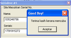
Let’s execute the program and type some name/serial to see what’s going on:

cme2-1

Okay, we can see the ‘Bad Boy’ message so let’s open the exe file with IDA and look for that string. Once found we can get all its references by pressing Ctrl+X and see where in the code it is being used.

CME2-2As you can see in the flow chart, there is a loop making some calculations and after that, the bad/good boy decission is taken. We could patch the jump so that we always get the Good Boy but the first rule was ‘no patching’ so we have to find out how the program works to write a keygen. So let’s focus in the inputs of the loop and the loop itself. As you can see below there are some calls to GetDlgItemTextA function which will get the strings from the DialogBox with the name / serial we have entered.

mov     esi, ds:GetDlgItemTextA
push    [ebp+hMem]      ; lpString
push    3E8h            ; nIDDlgItem
push    [ebp+hDlg]      ; hDlg
call    esi ; GetDlgItemTextA		<- Get the Name into hMem
push    [ebp+nMaxCount] ; nMaxCount
push    [ebp+arg_C]     ; lpString
push    edi             ; nIDDlgItem
push    [ebp+hDlg]      ; hDlg
call    esi ; GetDlgItemTextA		<- Get the serial into arg_C

Once the program has loaded our strings it’s going to make some calculations inside a loop:

; arg_4 holds the 0x1908 value
; ebx contains the length of our name
loc_4010CC:
mov     ecx, [ebp+hMem]
mov     edx, [ebp+arg_4]
add     edx, ebx			; edx+= name_length
movsx   ecx, byte ptr [eax+ecx]		; ecx = name[i]
imul    ecx, edx			; ecx = ecx * edx;
inc     eax				; i++;
mov     [ebp+arg_4], ecx
cmp     eax, ebx			; i == name_length?
jl      short loc_4010CC		; no -> loop

When this simple algorithm’s finished it’s got its output at arg_4 variable. Let’s see the next piece of code to see what our program does with it:

push    [ebp+arg_C]     ; char *
call    _atoi
pop     ecx				; eax = atoi(input_serial)
mov     ecx, [ebp+arg_4]		; get our computed value
push    0               ; uType
xor     ecx, 0A9F9FAh			; value ^= 0xA9F9FA;
cmp     ecx, eax			; do they match?
jnz     short BadBoy			; no -> bad boy
push    offset aGoodBoy ; "Good Boy!"
push    offset aTerimaKasihKer ; "Terima kasih kerana mencuba"
jmp     short loc_401111

Simple. The computed value is XOR’ed with 0xA9F9FA and then it is compared with the atoi() of the serial. If both values match then we get the good boy. Putting this all together we can now write a valid keygen for this program. Here it is the C source code of the simple keygen I wrote:

int main(int argc, char **argv)
{
	int namelength, i, serial=0x1908;
	char *name = argv[1];

	if(argc!=2)
	{
		printf("Usage: %s n",argv[0]);
		exit(1);
	}

	namelength=strlen(name);
	if(namelength < 5)
	{
		printf("Name must be at least 5 characters longn");
		exit(1);
	}

	for(i=0;i<namelength;i++)
	{
		serial+=namelength;
		serial*=name[i];
	}
	serial^=0xA9F9FA;
	printf("Serial: %dn",serial);
	return 1;
}


daniel@gargamel:~/crackme2$./keygen_cme2 daniel
Serial: -1860565822

cme2-3


daniel@gargamel:~/crackme2$./keygen_cme2 535246756
Serial: 1791915272

cme2-4

Done!
This is an easy and good one for your first steps at RE because it’s got no protections and you have to reverse a simple algorithm.

Hope you found this article useful.
Regards,
Daniel

Reverse Engineering

As you can see I’ve made another category inside the blog named ‘Reverse Engineering’. From the Wikipedia you can read:

Reverse engineering (RE) is the process of discovering the technological principles of a device, object or system through analysis of its structure, function and operation. It often involves taking something (e.g. a mechanical device, electronic component, or software program) apart and analyzing its workings in detail, usually to try to make a new device or program that does the same thing without copying anything from the original.

I’m really interested in security related to both software and hardware and this is the reason why I like Reverse Engineering so much. I am not a guru of this art though but I try some challenges from time to time (most of them from http://www.crackmes.de) specially those who include some kind of crypto protection.

In this category I will write some tutorials of the crackmes I manage to solve. So I’d recommend to all of you who are interested in RE to keep an eye on my blog and crackmes.de as well.

Regards,

Daniel

ARM Architecture. Design and Optimization.

I have worked on several platforms based on ARM cores: ARM7, ARM9 and XScale. ARM architecture has been present in more than 2 billion embedded products over the last 10 years, ranging from cell phones to automotive braking systems. I think ARM architecture is great for embedded computers and I needed to learn it so that I could get its best.

ARM System Developer’s Guide

The best book I found on this is ‘ARM System Developer’s Guide’ by Andrew Sloss (ARM Inc.), Dominic Symes (ARM Ltd.) and Chris Wright (Ultimodule Inc.). It covers all the ARM cores, XScale processors, demonstrates how to implement DSP algorithms, describes cache technologies that surround the ARM cores, as well as efficient memory management techniques.

Among the tasks I’ve had to deal with I’d point out Artificial Vision and Vocoders implementation for being computationally expensive.

In vocoders implementation and optimization case, I had to face some large of Digital Signal Processing issues which leaded me to write assembly code in order to get the best performance. Also I had to focus in the cache usage because it can speed up the execution time amazingly. Not to mention avoiding pipeline stalls and efficient use of the registers. The mentioned book covers all these topics both with theory and practical examples. There’s a dedicated chapter about DSP which even includes source code ready to use.

Even if you don’t need to write assembly code you can learn how to write efficient C code for ARM. I will show a simple example which can improve ‘intensive loop’ codes:

int checksum(int *data)
{
	unsigned int i;
	int sum=0;
	for(i=0; i<64; i++)
	{
		sum+=(*data++);
	}
}

This compiles to:

	mov	r2,r0		; r2=data
	mov	r0,#0		; sum=0
	mov	r1,#0		; i=0
checksum_loop
	ldr	r3,[r2],#4	; r3 = *(data++)
	add	r1,r1,#1	; i++
	cmp	r1,#0x40	; compare i,64
	add	r0,r3,r0	; sum+=r3
	bcc	checksum_loop	; if(i<64) loop
	mov	pc,lr		; return sum

The above code is not efficient, we can avoid the 3 steps loop: ADD 1 to i, comparison and the conditional branch instruction.
Instead:

int checksum_eff(int *data)
{
	unsigned int i;
	int sum=0;
	for(i=64; i!=0; i----)
	{
		sum += *(data++);
	}
	return sum;
}

As you can see, we just rewrote the loop to be descendent rathern than the previous incrementing loop. Let’s have a look at the compiled code:

	mov	r2,r0			; r2=data
	mov	r0,#0			; sum=0
	mov	r1,#0x40		; i=64
checksum_2_loop
	ldr	r3,[r2],#4		; r3=*(data++)
	subs	r1,r1,#1		; i-- and set flags
	add	r0,r3,r0		; sum+=r3
	bne	checksum_2_loop		; if (i!=0) loop
	mov	pc,lr			; return sum

As you can see, the loop work is done entirely by the subs and bne instructions. The comparison with zero is free since the result is stored in the condition flags. Thus we can see that it’s more efficient to make decrementing loops in ARM than incrementing ones.

Let’s have a look at the way one could have written the same function in C without taking efficiency into account:

int checksum(int *cata)
{
	char *i;
	int sum=0;
	for(i=0; i<64;i++)
	{
		sum += data[i];
	}
}

And the compiler output:

	mov	r2,r0			;r2=data
	mov	r0,#0			;sum=0
	mov	r1,#0			;i=0
checksum_loop
	ldr	r3,[r2,r1,lsl #2]	;r3=data[i]
	add	r1,r1,#1		;r1=i+1
	and	r1,r1,#0xff		;i=(char)i
	cmp	r1,#0x40		;compare i and 64
	add	r0,r3,r0		;sum+=r3
	bcc	checksum_loop		;if(i<64) loop
	mov	pc,lr			;return sum

At first, one may think that declaring i as char uses less register space or less space on the ARM stack than an int. On ARM these assumptions are wrong and that’s why the output code includes the AND instruction with 0xFF which actually slows the execution without saving space. So our checksum_eff function is pretty much faster without not so much effort just by knowing a little bit about ARM architecture.

Rewriting C functions is the first thing that should be done when optimizing before digging down into assembly. Special care must be taken in those functions with nested loops or with too many iterations. It’s also useful some profiling tool like Intel VTune Performance Analyzer to check if all our optimizations are really optimizations and how much we have speeded its execution up.

Hope you found this article useful,

Daniel