After my first contact with the RTL-SDR a couple of days ago , I’ve been researching a bit more and found this fantastic blog post by Adam Laurie which describes how to use a TI Chronos development kit to send arbitrary sub-1GHz signals. It happens that I had such a kit so I decided to emulate another garage door opener, but this time using RFCat.
Loading RFCat firmware into the Chronos USB Dongle
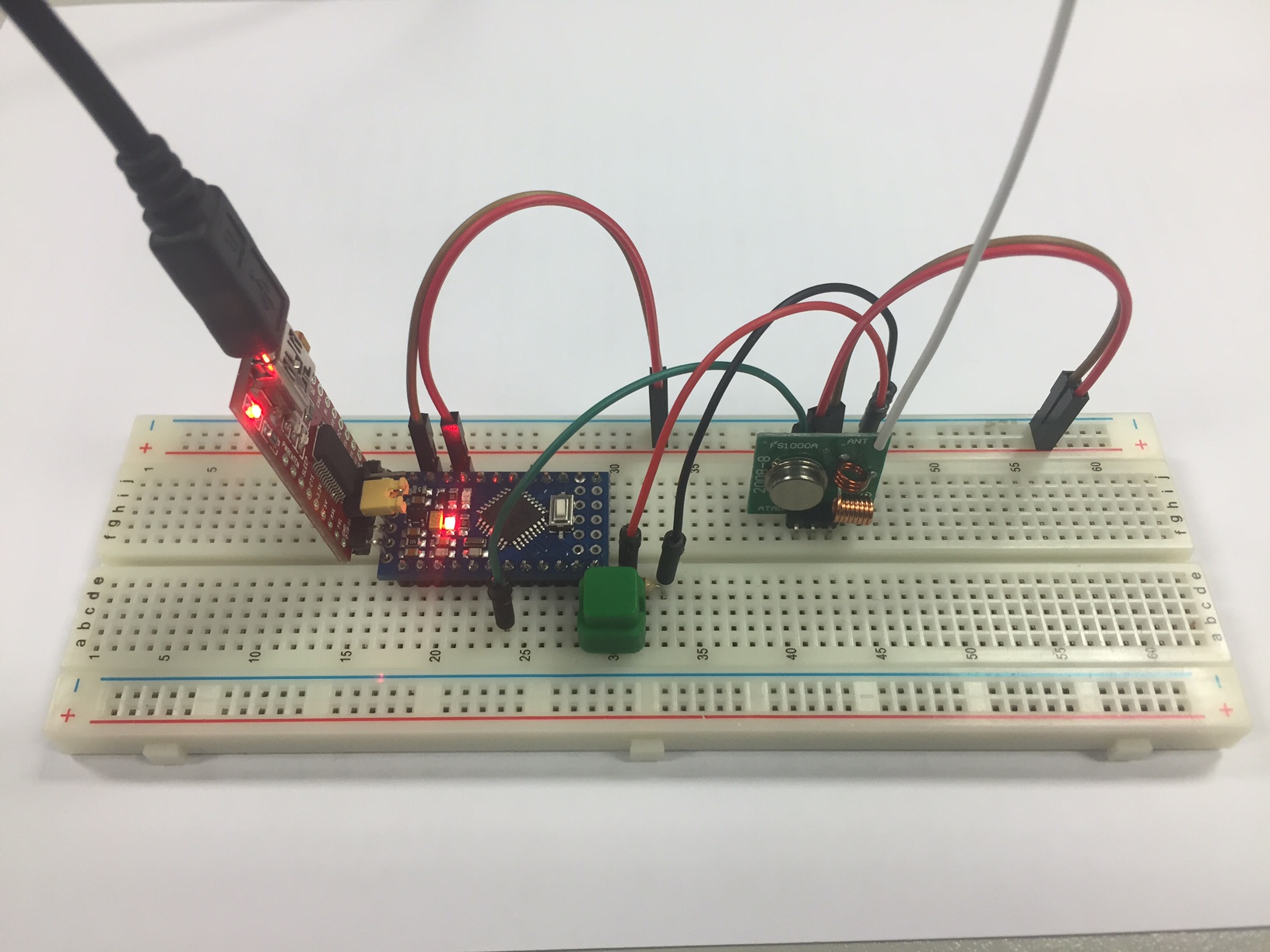
First thing I did was to flash the USB dongle with the RFCat firmware so that I could emulate the remote from a python script. As I had a CC Programmer handy (you can also use GoodFET), I wired it up by following the diagram below and flashed the RFCat bin for the ez Chronos dongle using the SmartRF Flash Programmer tool.
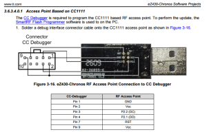
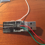

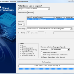
You can either flash the dongle with the RFCat binary itself or with the CC Bootloader which will allow you to update the dongle further without having to use the JTAG. I took the second approach so after flashing the bootloader, you’ll need to flash the actual RFCat firmware:
python bootloader.py /dev/ttyACM0 download RfCatChronosCCBootloader-150225.hex
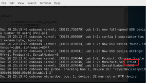
After successfully flashing the dongle, it should show up as “RFCat” and you should be able to communicate with it from the rfcat interpreter:
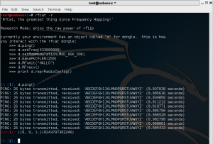
As the communication with the dongle was good, it was time to analyze the signal sent by the remote and write some code to replay it using RFCat.
Signal Analysis
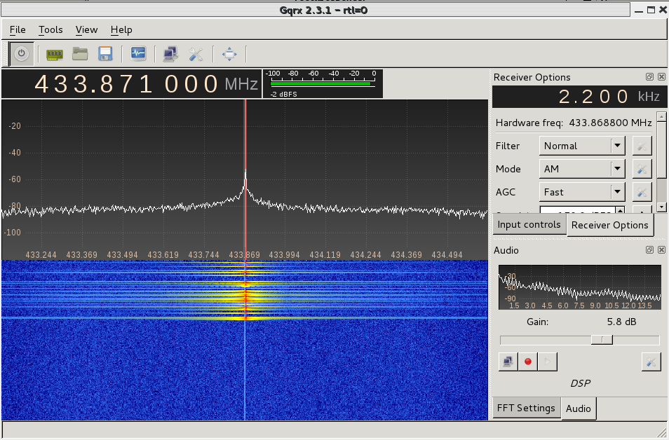
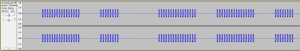
For the analysis part, I used the SDR# tool for Windows: tuned the right frequency (433.92MHz) and saved the signal into a Wav file for later analysis with Audacity.
![]()
It’s a fixed code and looks pretty straightforward: short and long pulses. We can estimate the length of each type by measuring the number of samples. In this case, short pulses took 3000 samples or 1200us (sample rate was 2.4Ms on SDRSharp).
A good way to represent the signal is to encode the “long pulse plus silence” as “1” and the “short pulse plus silence” as “0”. Then, the frame would look like this:
1 0 1 1 0 1 1 1 1 1 1 0 0 0 0 0 1 0 1 1 0 0 1 1 0 0 1 1 0 0 1 1 1
As the “1” is formed by two high and one low short pulses of equal duration, we can express it as “110”. Similarly, our “0” can be represented as “100” and the frame now would be:
110 100 110 110 100 110 110 110 110 110 110 100 100 100 100 100
110 100 110 110 100 100 110 110 100 100 110 110 100 100 110 110 110
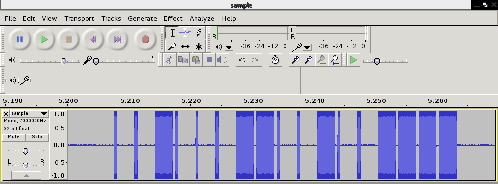
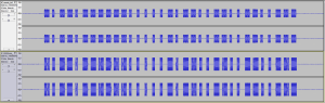
However, if we zoom in on the signal, we can see that the pulses are divided in more little pulses that we’ll need to encode in some way:
So, the final frame would make us rewrite the previous one changing every “1” bit by \xAA\xAA and every “0” bit by \x00\x00 to maintain the length of each bit (see code below). The duration of each bit is now about 80 us.
Replaying signal with RFCat
Now that we have analyzed the signal, it’s time to write a Python script to interface the RFCat dongle so that it generates the frames accordingly. Afterwards, we’ll capture the signal back to make sure that both the waveform and timing are correct:
from rflib import*
from time import sleep

pkt = '\xAA\xAA\xAA\xAA\x00\x00\xAA\xAA\x00\x00\x00\x00\xAA\xAA\xAA\xAA\x00\x00\xAA\xAA\xAA\xAA\x00\x00\xAA\xAA\x00\x00\x00\x00\xAA\xAA\xAA\xAA\x00\x00\xAA\xAA\xAA\xAA\x00\x00\xAA\xAA\xAA\xAA\x00\x00\xAA\xAA\xAA\xAA\x00\x00\xAA\xAA\xAA\xAA\x00\x00\xAA\xAA\xAA\xAA\x00\x00\xAA\xAA\x00\x00\x00\x00\xAA\xAA\x00\x00\x00\x00\xAA\xAA\x00\x00\x00\x00\xAA\xAA\x00\x00\x00\x00\xAA\xAA\x00\x00\x00\x00\xAA\xAA\xAA\xAA\x00\x00\xAA\xAA\x00\x00\x00\x00\xAA\xAA\xAA\xAA\x00\x00\xAA\xAA\xAA\xAA\x00\x00\xAA\xAA\x00\x00\x00\x00\xAA\xAA\x00\x00\x00\x00\xAA\xAA\xAA\xAA\x00\x00\xAA\xAA\xAA\xAA\x00\x00\xAA\xAA\x00\x00\x00\x00\xAA\xAA\x00\x00\x00\x00\xAA\xAA\xAA\xAA\x00\x00\xAA\xAA\xAA\xAA\x00\x00\xAA\xAA\x00\x00\x00\x00\xAA\xAA\x00\x00\x00\x00\xAA\xAA\xAA\xAA\x00\x00\xAA\xAA\xAA\xAA\x00\x00\xAA\xAA\xAA\xAA\x00\x00'

NUM_REPS	= 10		# times the frame will be sent
DELAY 		= 0.02	# seconds between frames

try:

	d = RfCat()
	d.setMdmModulation(MOD_ASK_OOK)
	d.setFreq(433290000)	# Set freq to 433.92MHz
	d.setMaxPower()
	d.setMdmSyncMode(0)		# Don't send preamble/sync word
	d.setMdmDRate((int)(1.0/0.000080))	# Our bits are 80us long
 	d.makePktFLEN(len(pkt))

	print "Sending frames "
	for i in range(0,NUM_REPS):
		sys.stdout.write(".")
		d.RFxmit(pkt)
		sleep(DELAY)
	print " Done\n"
	d.setModeIDLE()

except Exception, e:
	sys.exit("Error %s" % str(e))
Now let’s run the script and capture the signal back with SDR# to check if it looks like it should:
![]()
The first picture shows both our reference signal (sent by the remote) and the one generated with the RFCat dongle. The second picture shows the detail of each bit. As expected, it opened the door although the output power seemed a bit too low . Maybe there’s a hack to improve the antenna of the Chronos dongle? 🙂
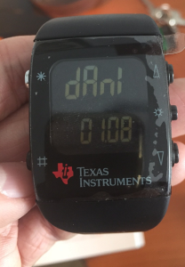
Replaying the signal with the Chronos Sports Watch
Okay, the hard part is over so let’s have some fun and replay the signal directly from our wrist 🙂
The ChronIC project is pretty much like the RFCat firmware but can loaded directly into the Chronos Sports Watch so that pre-loaded signals can be sent just by pressing the up/down buttons. I modified the code to make the watch send our frame every time I pressed the UP button. Below is the code that will do the magic, and a couple of useful Python functions (from Adam’s code) to calculate the register values for your bitrate and frequency:
 def setfreq(freq):
	mhz= 26
	freqmult = (0x10000 / 1000000.0) / mhz
	num = int(freq * freqmult)
	freq0= num & 0xff
	payload= chr(freq0)
	freq1= (num >> 8) & 0xff
	payload += chr(freq1)
	freq2= (num >> 16) & 0xff
	payload += chr(freq2)
	print '- FREQ2: %02x FREQ1: %02x FREQ0: %02x -' % (freq2, freq1, freq0)

def setdatarate(drate):
	mhz= 26
	drate_e = None
	drate_m = None
	for e in range(16):
		m = int((drate * pow(2,28) / (pow(2,e)* (mhz*1000000.0))-256) + .5)        # rounded evenly
		if m < 256:
			drate_e = e
			drate_m = m
			break
	if drate_e is None:
		return False, None
	drate = 1000000.0 * mhz * (256+drate_m) * pow(2,drate_e) / pow(2,28)
	print 'drate_e: %02x  drate_m: %02x' %(drate_e,drate_m)
void config_garage(u8 line)
{
	// gap between data pulses
	//Button_Delay= 0;
	Button_Delay= 20;
	// how many times to send per button press
	Button_Repeat= 10;

	// set button content

	Up_Buttons= 1;
	// packet length
	Button_Up_Data[0][0]= 198;
	// payload
	memcpy(&Button_Up_Data[0][1],"\xAA,\xAA,\xAA,\xAA,\x00,\x00,\xAA,\xAA,\
 \x00,\x00,\x00,\x00,\xAA,\xAA,\xAA,\xAA,\x00,\x00,\xAA,\xAA,\xAA,\xAA,\x00,\x00,\
 \xAA,\xAA,\x00,\x00,\x00,\x00,\xAA,\xAA,\xAA,\xAA,\x00,\x00,\xAA,\xAA,\xAA,\xAA,\
 \x00,\x00,\xAA,\xAA,\xAA,\xAA,\x00,\x00,\xAA,\xAA,\xAA,\xAA,\x00,\x00,\xAA,\xAA,\
 \xAA,\xAA,\x00,\x00,\xAA,\xAA,\xAA,\xAA,\x00,\x00,\xAA,\xAA,\x00,\x00,\x00,\x00,\
 \xAA,\xAA,\x00,\x00,\x00,\x00,\xAA,\xAA,\x00,\x00,\x00,\x00,\xAA,\xAA,\x00,\x00,\
 \x00,\x00,\xAA,\xAA,\x00,\x00,\x00,\x00,\xAA,\xAA,\xAA,\xAA,\x00,\x00,\xAA,\xAA,\
 \x00,\x00,\x00,\x00,\xAA,\xAA,\xAA,\xAA,\x00,\x00,\xAA,\xAA,\xAA,\xAA,\x00,\x00,\
 \xAA,\xAA,\x00,\x00,\x00,\x00,\xAA,\xAA,\x00,\x00,\x00,\x00,\xAA,\xAA,\xAA,\xAA,\
 \x00,\x00,\xAA,\xAA,\xAA,\xAA,\x00,\x00,\xAA,\xAA,\x00,\x00,\x00,\x00,\xAA,\xAA,\
 \x00,\x00,\x00,\x00,\xAA,\xAA,\xAA,\xAA,\x00,\x00,\xAA,\xAA,\xAA,\xAA,\x00,\x00,\
 \xAA,\xAA,\x00,\x00,\x00,\x00,\xAA,\xAA,\x00,\x00,\x00,\x00,\xAA,\xAA,\xAA,\xAA,\
 \x00,\x00,\xAA,\xAA,\xAA,\xAA,\x00,\x00,\xAA,\xAA,\xAA,\xAA,\x00,\x00",Button_Up_Data[0][0]);

	Down_Buttons= 0;

	// set frequency (433920000)
	ChronicRF.freq0= 0x71;
	ChronicRF.freq1= 0xB0;
	ChronicRF.freq2= 0x10;

	// set data rate (pulsewidth 80us)
	// drate_m
	ChronicRF.mdmcfg3= 0xf8;
	// drate_e
	ChronicRF.mdmcfg4 &= 0xf0;
	ChronicRF.mdmcfg4 |= 8;

	// set modulation
	ChronicRF.mdmcfg2 &= ~MASK_MOD_FORMAT;
	ChronicRF.mdmcfg2 |= MOD_OOK;
	// set sync mode
	ChronicRF.mdmcfg2 &= ~MASK_SYNC_MODE;
	ChronicRF.mdmcfg2 |= SYNC_MODE_NONE;
	// set manchester false
	ChronicRF.mdmcfg2 &= ~MASK_MANCHESTER;
	display_symbol(LCD_ICON_RECORD, SEG_ON);
	Emulation_Mode= EMULATION_MODE_GARAGE;
}
After building the code with Code Composer and loading it into the Watch with the JTAG included in the kit, a new menu is available and the signal’s going to be sent every time we press the UP button.
🙂 🙂
All the information in this blog is for educational purposes only. You shall not misuse the information to gain unauthorized access.