After the last two posts, I decided to build a simple PCB to handle various remotes in a single device and also serve as a “general purpose keyfob”. I’ve built it around a PIC12F1840 microcontroller which I had handy. This microcontroller includes an internal oscillator so the external components were reduced to a minimum: just the radio transmitter, some push-buttons and a LED.
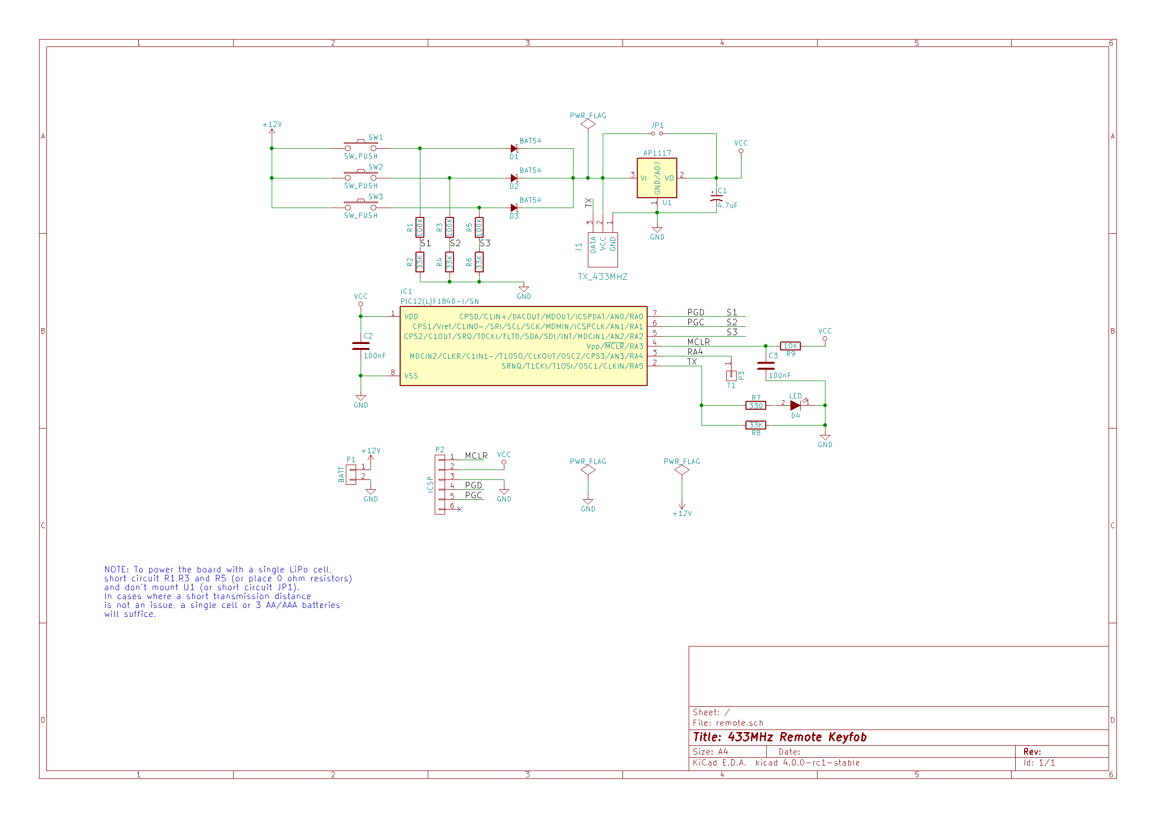
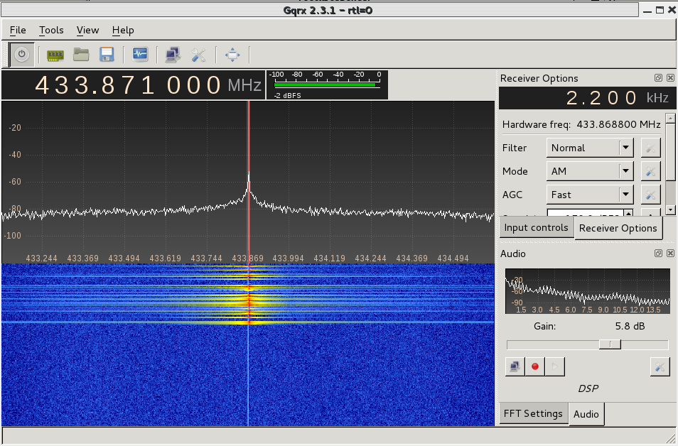
Initially, I aimed to power the board directly from a 1-cell Lipo battery (or 3 AA/AAA) but I included support for a higher voltage supply just in case the transmission power was too weak. If you want to power the keyfob with a higher voltage, just solder the regulator and adjust the resistors (R1, R3 and R5) so that the PIC reads no more than VCC volts at its inputs. For my application, it works just fine with a 4.2 battery and I get around 30 meters of transmission distance.
The board remains unpowered until the user presses a button. At that time, the microcontroller boots up, reads which of the button’s been pressed and executes the action until released. Theoretically, a single battery should last a few years.
Below you can download the Kicad files so that you can modify anything, as well as the gerber files to order it your own. The transmission module can be easily found on many sites for less than $2.
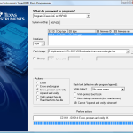
Below is the C code for the microcontroller that can be compiled using the free version of MPLAB IDE. It’s an example of how to send a different command depending on which button is pressed by the user.
/*
* File: main.c
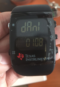
* Author: Dani
*
* Created on 7 de marzo de 2016, 20:06
*/
#include <stdio.h>
#include <stdlib.h>
#include <xc.h>
#define _XTAL_FREQ 16000000
// #pragma config statements should precede project file includes.
// Use project enums instead of #define for ON and OFF.
// CONFIG1
#pragma config FOSC = INTOSC // Oscillator Selection (INTOSC oscillator: I/O function on CLKIN pin)
#pragma config WDTE = OFF // Watchdog Timer Enable (WDT disabled)
#pragma config PWRTE = OFF // Power-up Timer Enable (PWRT disabled)
#pragma config MCLRE = ON // MCLR Pin Function Select (MCLR/VPP pin function is MCLR)
#pragma config CP = OFF // Flash Program Memory Code Protection (Program memory code protection is disabled)
#pragma config CPD = OFF // Data Memory Code Protection (Data memory code protection is disabled)
#pragma config BOREN = ON // Brown-out Reset Enable (Brown-out Reset enabled)
#pragma config CLKOUTEN = OFF // Clock Out Enable (CLKOUT function is disabled. I/O or oscillator function on the CLKOUT pin)
#pragma config IESO = ON // Internal/External Switchover (Internal/External Switchover mode is enabled)
#pragma config FCMEN = ON // Fail-Safe Clock Monitor Enable (Fail-Safe Clock Monitor is enabled)
// CONFIG2
#pragma config WRT = OFF // Flash Memory Self-Write Protection (Write protection off)
#pragma config PLLEN = ON // PLL Enable (4x PLL enabled)
#pragma config STVREN = ON // Stack Overflow/Underflow Reset Enable (Stack Overflow or Underflow will cause a Reset)
#pragma config BORV = LO // Brown-out Reset Voltage Selection (Brown-out Reset Voltage (Vbor), low trip point selected.)
#pragma config LVP = ON // Low-Voltage Programming Enable (Low-voltage programming enabled)
/*
*
*/
/*
* RA0 = S1 (INPUT) LEFT
* RA1 = S2 (INPUT) INH
* RA2 = S3 (INPUT) RIGHT
* RA5 = Tx (OUTPUT)
*
* RA4 = Testpoint
*
*/
#define TX_PIN RA5
#define PKT_LENGTH 48
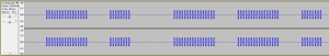
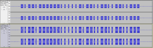
const unsigned char left_pkt[] = {0x00,0x00,0x00,0x00,0xAA,0x00,0x00,0x00,0xAA,0xAA,0xAA,0xAA,0x00,0x00,0x00,0x00,0xAA,0x00,0x00,0x00,0xAA,0xAA,0xAA,0xAA,0x00,0x00,0x00,0x00,0xAA,0x00,0x00,0x00,0xAA,0xAA,0xAA,0xAA,0x00,0x00,0x00,0x00,0xAA,0x00,0x00,0x00,0xAA,0xAA,0xAA,0xAA};
const unsigned char right_pkt[] = {0x00,0x00,0x00,0x00,0xAA,0x00,0x00,0x00,0xAA,0xAA,0xAA,0xAA,0x00,0x00,0x00,0x00,0xAA,0x00,0x00,0x00,0xAA,0xAA,0xAA,0xAA,0x00,0x00,0x00,0x00,0xAA,0x00,0x00,0x00,0xAA,0xAA,0xAA,0xAA,0x00,0x00,0x00,0x00,0xAA,0xAA,0xAA,0xAA,0x00,000,0x00,0x00};
#define BITDELAY 70
#define delayMicroseconds __delay_us
void tx_frame(const unsigned char *ptr, unsigned int length)
{
unsigned int i;
for(i=0;i<length;i++)
{
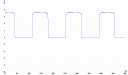
TX_PIN = ((ptr[i] & 0x80) != 0); delayMicroseconds(BITDELAY);
TX_PIN = ((ptr[i] & 0x40) != 0); delayMicroseconds(BITDELAY);
TX_PIN = ((ptr[i] & 0x20) != 0); delayMicroseconds(BITDELAY);
TX_PIN = ((ptr[i] & 0x10) != 0); delayMicroseconds(BITDELAY);
TX_PIN = ((ptr[i] & 0x08) != 0); delayMicroseconds(BITDELAY);
TX_PIN = ((ptr[i] & 0x04) != 0); delayMicroseconds(BITDELAY);
TX_PIN = ((ptr[i] & 0x02) != 0); delayMicroseconds(BITDELAY);
TX_PIN = ((ptr[i] & 0x01) != 0); delayMicroseconds(BITDELAY);
}
__delay_ms(20);
}
int main(int argc, char** argv)
{
unsigned char left=0, right=0, extra=0;
OSCCON |= (0x0F<<3); // Internal oscillator @ 16MHz
ANSELA = 0; // No analog inputs
WPUA=0; // No internal pullups
TRISA |= ((1<<0)|(1<<1)|(1<<2)); // Buttons as Inputs
TRISA &= ~(1<<4); // RA4 (testpoint) as Output PIN
RA4=0;
// Allow some time to set things up
__delay_ms(100);
//Check what actions are requested:
if((PORTA & 1) == 1) left = 1;
if((PORTA & 2) == 2) extra = 1;
if((PORTA & 4) == 4) right = 1;
while(1)
{
if(left==1)
tx_frame(left_pkt,PKT_LENGTH);
if(right==1)
tx_frame(right_pkt,PKT_LENGTH);
}
return (EXIT_SUCCESS);
}
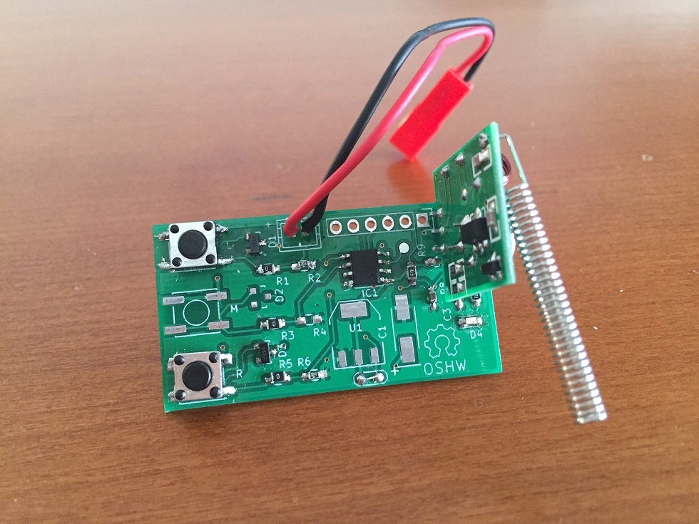
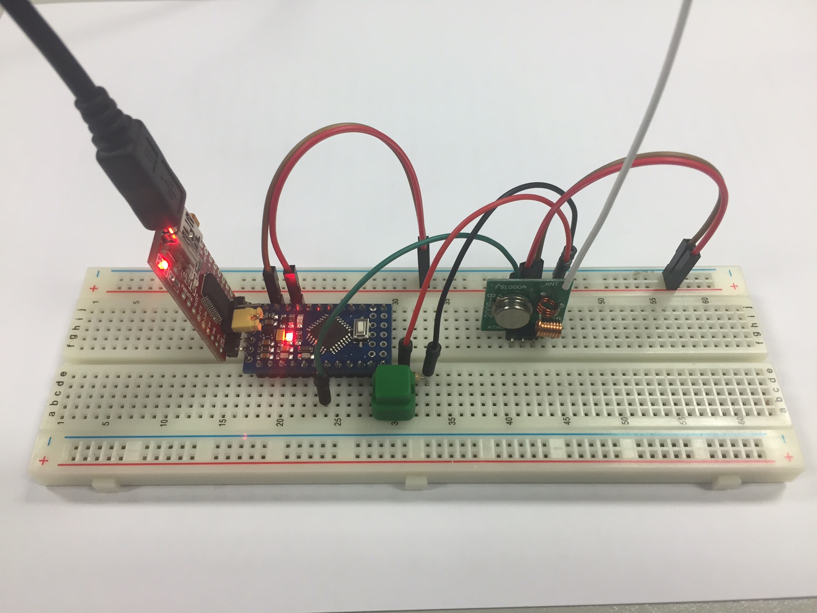
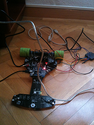
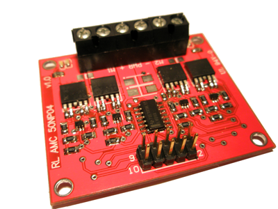
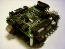
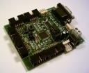
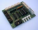
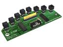
Below, a couple of pictures of the board with the transmission module attached:

I’ll build a second version of the board to fit a 3-button case or maybe I get one case 3D printed 🙂


