Month: January 2008

Crackme 3 – RSA

This KeyGenMe is pretty nice since it’s got some public key cryptography inside it.

You can download the original exe file, my KeyGen source file and the tools used from here.

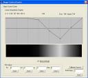
The goal is to break an RSA protection to build a valid KeyGen. Let’s start by opening the executable file with PeID and its Krypto Analyzer Plugin:

peid-pallas

As you can see there is some calls to Miracl library functions and it could identify an SHA hash function inside the binary. Let’s keep this in mind while analyzing further with IDA. I recommend you to download some Miracl signatures for IDA so that it can identify the library functions for us.

Open the KeyGenMe with IDA and locate the GetDlgItemTextA call which will retrieve our typed Serial. Analyze the code around it to see what’s going on:

.text:004027B2                 push    [ebp+var_488]
.text:004027B8                 push    [ebp+var_490]
.text:004027BE                 push    [ebp+var_494]
.text:004027C4                 push    [ebp+var_498]
.text:004027CA                 call      miracl_powmod

Powmod function prototype:

void 	powmod (big x, big y, big n, big w);

The powmod function computes w = x^y (mod n). It actually looks like RSA algorithm where x is the serial we typed in the TextBox. Now I will rename the vars for the sake of clarity:

.text:004027B2 push    [ebp+result]
.text:004027B8 push    [ebp+modulus]
.text:004027BE push    [ebp+public_key]
.text:004027C4 push    [ebp+INPUT_SERIAL]
.text:004027CA call      miracl_powmod

All these variables pushed onto the stack are mirvars and since we know its structure we can have a look at them to figure out their size:

debug025:00914F58 dword_914F58 dd 20h
debug025:00914F5C dd offset unk_914F64
debug025:00914F60 db    0
debug025:00914F61 db    0
debug025:00914F62 db    0
debug025:00914F63 db    0
debug025:00914F64 unk_914F64 db  49h ;

The first dword of a mirvar represents its length in 32bit words. So 20h means that the modulus is 1024 bits long.

From the pointer above (0x00914F64) we can take out the modulus value:

N=6601E15E4F6C572B0B38EDF792D426BBA6DEDB98D600C5763C5F2123A361F
49C0CAEA628887077DE01D1DE826D2496DF38802024BC00A64940C8EAB4F1D8
60443C8DE0CEB6B7611888F660B022AA32C3450BC2B6E035D6354654E8EF4666
31F0D180E978DB6960EB4061EAB52D0B281C580B8DA8FE76AB54D5AD85223DB
E1449

Repeating this process we will extract the public exponent: E in RSA scheme.

E=2B7893403C69D8FEB1C4A36D219298438722F2CEB82792230A0B9B8F2DD680
4DB9E64381AEDC6B070AF501522781368C6D76A176223F98FADBFF5F26B5FBAD
814C62143C2A430667CEDDD19C91F20E8EDCAA2A1773F71A18DA3CFAD34B75A6
23724349417E963347C9971E0EFB6E613691F2715523A53AA7CEC4E970584135F3

These two values were hardcoded into the original file each byte XOR’ed with 0x01.

If we scroll up in the disassembly we will see some interesting code:

.text:0040263D call    ds:GetVolumeInformationA
.text:00402643 push    [ebp+VolumeSerialNumber]
.text:00402649 push    offset asc_40D0FC ; "%x"
.text:0040264E lea     eax, [ebp+strVolumeSerialNumber]
.text:00402654 push    eax             ; char *
.text:00402655 call    _sprintf

Interesting, the above code is retrieving our HDD serial number and printing it as an hex ascii string into a local variable.
Then some modifications to this string will be applied:

With the help of Krypto Analyzer we could locate the SHA routine starting at 0x00401030 address which will be soon called
after retrieving the HDD serial number. Having a further look into xrefs to the identified SHA functions we may recognize
a typical hash stucture:

SHA_Init	@	0x00401000
SHA_Process	@	0x004023A4
SHA_Result	@	0x00402435

Ok, the HDD serial number is retrieved, printed to an ASCII hex string and then hashed. I checked the hash with a standard SHA-1 implementation and it differed from the 20-byte hash calculated by the keygenme. So I checked also SHA-0 which just differs from SHA-1 in a rotation but it didn’t match either. I didn’t want to waste so much time in identifying the used hash function so I decided to rip out the code from the binary itself (see sha.asm file in my sources) and build an object which will be linked against my KeyGen to produce exactly the same hash value.

After the hash of our HDD serial string was computed, the KeygenMe creates some miracl variables and a bignum which I’ll call ‘A’

A = 920CC8F0512FB63B8C2F89397A129BAA3D663BD1890C8EE23AAC836A316E231B
C = hash(strHDD_Serial) ^ 7 (mod A)

Now, the serial we typed in the TextBox will be the object of the RSA computation:

INPUT_SERIAL ^ E (mod N)

and compared with the previously calculated value C. If both match, then we have entered the right Serial.

So we have to find a serial which satisfies: C = INPUT_SERIAL ^ E (mod N) given C, E and N. This is clearly an RSA scheme:

RSA Encryption
rsa-encryption

RSA Decryption
rsa-decryption1

rsa-decryption2

Thus:

INPUT_SERIAL = C ^ D (MOD N)

We can see that to find a valid Serial we must know D (private exponent) and therefore we’ve got to compute it somehow.

N = P*Q, where P and Q are two large primes
E*D = 1 (MOD P-1)
E*D = 1 (MOD Q-1)
So, given P,Q and E we could easily obtain D. The problem is that factorizing N (1024-bit number) into P*Q is not feasible since it would take a nice amount of years.

There are some vulnerabilities in RSA algorithm regarding the size of the chosen exponents. One of them is exploited by the Wiener Attack which is able to find in polynomial time the secret exponent (D) if two conditions are given:

  • Q < P and P < 2*Q
  • D < 1/3*N^1/4

Sometimes low private exponents are chosen to speed up the decryption process. However if it falls inside these bounds we can compute it very fast. I will use the RAT (RSA Attacking Tool) by bLaCk-eye which is a very powerful tool to attack RSA in several ways. Besides he distributes this application with its source code and I recommend you to have a look at it.

If we give N and E to RAT it will immediately say the value of the private exponent which happens to be:

pallas-rat

D = B33F

Thus, we just have to code the following actions in our KeyGen:

  • Retrieve the HDD serial number
  • Compute C=hash(strHDD_Serial) ^ 7 (mod A)
  • Serial = C^D (mod N)

Please note that only the first 8 bytes of the hash output are used for the above calculation.

pallaskeygen

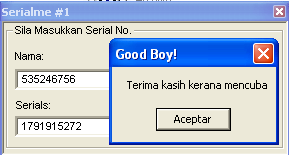
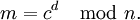
And paste this number into Pallas KeyGenMe:

pallas-ok


For a further understanding of the process have a look at the source code included.

ARM Development Board – LPC2138-01

LPC2138-01

I have designed a new development board which is supposed to be used in many of the projects I am/will be involved in. It’s been built around an NXP LPC2138 microcontroller which has the following main features:

  • 16/32 bit ARM7TDMI-S microcontroller (LQFP64 package)
  • 32 KB of internal SRAM and 512 KB of on-chip flash program memory. 128-bit wide interface/accelerator enables high-speed 60 Mhz operation.
  • In-System Programming/In-Application Programming (ISP/IAP) via on-chip bootloader software. Single flash sector or full chip erase in 400 ms and programming of 256 B in 1 ms.
  • Two 8-channel 10-bit ADCs with conversion times as low as 2.44 us per channel.
  • Two 32-bit timers/external event counters (with four capture and four compare channels each), PWM unit (six outputs) and watchdog.
  • Multiple serial interfaces including two UARTs (16C550), two Fast I2C-bus (400 kbit/s), SPI and SSP with buffering and variable data length capabilities.
  • Vectored interrupt controller with configurable priorities and vector addresses.
  • Up to forty-seven 5 V tolerant general purpose I/O pins in tiny LQFP64 package.
  • Up to nine edge or level sensitive external interrupt pins available.
  • 60 MHz maximum CPU clock available from programmable on-chip PLL with settling time of 100 us.
  • On-chip integrated oscillator operates with external crystal in range of 1 MHz to 30 MHz and with external oscillator up to 50 MHz.
  • Power saving modes include Idle and Power-down.
  • Individual enable/disable of peripheral functions as well as peripheral clock scaling down for additional power optimization.
  • Processor wake-up from Power-down mode via external interrupt or BOD.
  • Single power supply chip with POR and BOD circuits:
    • CPU operating voltage range of 3.0 V to 3.6 V (3.3 V +- 10 pct) with 5 V tolerant I/O pads.

This microcontroller is suitable for most of my projects due to its high processing power (up to 60 MIPS) and its large amount of memory. Also, the board itself has some kind of features that I couldn’t find in any other development board:

  • Audio playing support with earphones connector. Connected to the DAC output of the microcontroller through an audio amplifier circuit. It is possible to use the DAC output for another purposes.
  • Audio recording support with microphone connector. Connected to one of the ADCs channels of the microcontroller through an audio amplifier and signal conditioning circuit. It is possible to use the ADC input for another purposes.
  • Selectable power supply input: directly from USB or from external battery for standalone applications (Vin ranging from 3.3V to 20V).
  • RS232 interface through DB9 connector.
  • USB communication through USB Type-B connector (on-board USB-Serial converter). RX and TX leds.
  • 8 General Purpose LED’s connected to the microcontroller through an output buffer which can be disabled through a jumper in case that these GPIO pins are needed.
  • Reset Button
  • General purpose button connected to one of the external interrupts of the microcontroller.
  • In Circuit Programming interface up to 115200 bps.
  • 12 MHz crystal for operation up to 60 MHz.
  • MMC/SD memory card interface connected to the SPI bus of the microcontroller.
  • Integrated Li-Ion / Li-Po Battery charger. It can charge batteries from USB or external power supply with LED charge indicators.
  • All the GPIO pins are available in the board. Including JTAG interface for programming / debugging in circuit.
  • Battery level monitoring. The input voltage is connected to one of the ADC inputs of the microcontroller through a voltage divisor so that it can be measured by software.

Software:

As the ARM architecture is being more and more popular there are lots of development tools available for all the platforms.

On Windows machines you can use WinARM which is a collection of tools to develop software for the ARM-family of controllers/processors including GNU C/C++ compiler (gcc / g++), GNU Binutils, GDB server, …

Most of these tools are part of GNU arm-elf toolchain distributions so you can easily develop /program the LPC2138 microcontroller under GNU/Linux.

Also, you can find some good commercial software for ARM microcontrollers/microprocessors like the ARM RealView Development Suite.

In some applications an RTOS (Real Time Operating System) is needed and there are some of them available for this microcontroller. I would stand out the following ones: FreeRTOS (free for non-commercial purposes) and RealView RL-ARM.

Daniel.


Crackme 2

This is a really easy crackme for Windows which I solved in no more than 5 minutes. I have chosen this one to make a simple tutorial for those who are starting with Reverse Engineering so here we go.

You can see the original crackme page here.

The rules from the author are:

1. NO PATCHING
2. Find Serial
3. Write Keygen
4. 😉 Enjoy

Let’s execute the program and type some name/serial to see what’s going on:

cme2-1

Okay, we can see the ‘Bad Boy’ message so let’s open the exe file with IDA and look for that string. Once found we can get all its references by pressing Ctrl+X and see where in the code it is being used.

CME2-2As you can see in the flow chart, there is a loop making some calculations and after that, the bad/good boy decission is taken. We could patch the jump so that we always get the Good Boy but the first rule was ‘no patching’ so we have to find out how the program works to write a keygen. So let’s focus in the inputs of the loop and the loop itself. As you can see below there are some calls to GetDlgItemTextA function which will get the strings from the DialogBox with the name / serial we have entered.

mov     esi, ds:GetDlgItemTextA
push    [ebp+hMem]      ; lpString
push    3E8h            ; nIDDlgItem
push    [ebp+hDlg]      ; hDlg
call    esi ; GetDlgItemTextA		<- Get the Name into hMem
push    [ebp+nMaxCount] ; nMaxCount
push    [ebp+arg_C]     ; lpString
push    edi             ; nIDDlgItem
push    [ebp+hDlg]      ; hDlg
call    esi ; GetDlgItemTextA		<- Get the serial into arg_C

Once the program has loaded our strings it’s going to make some calculations inside a loop:

; arg_4 holds the 0x1908 value
; ebx contains the length of our name
loc_4010CC:
mov     ecx, [ebp+hMem]
mov     edx, [ebp+arg_4]
add     edx, ebx			; edx+= name_length
movsx   ecx, byte ptr [eax+ecx]		; ecx = name[i]
imul    ecx, edx			; ecx = ecx * edx;
inc     eax				; i++;
mov     [ebp+arg_4], ecx
cmp     eax, ebx			; i == name_length?
jl      short loc_4010CC		; no -> loop

When this simple algorithm’s finished it’s got its output at arg_4 variable. Let’s see the next piece of code to see what our program does with it:

push    [ebp+arg_C]     ; char *
call    _atoi
pop     ecx				; eax = atoi(input_serial)
mov     ecx, [ebp+arg_4]		; get our computed value
push    0               ; uType
xor     ecx, 0A9F9FAh			; value ^= 0xA9F9FA;
cmp     ecx, eax			; do they match?
jnz     short BadBoy			; no -> bad boy
push    offset aGoodBoy ; "Good Boy!"
push    offset aTerimaKasihKer ; "Terima kasih kerana mencuba"
jmp     short loc_401111

Simple. The computed value is XOR’ed with 0xA9F9FA and then it is compared with the atoi() of the serial. If both values match then we get the good boy. Putting this all together we can now write a valid keygen for this program. Here it is the C source code of the simple keygen I wrote:

int main(int argc, char **argv)
{
	int namelength, i, serial=0x1908;
	char *name = argv[1];

	if(argc!=2)
	{
		printf("Usage: %s n",argv[0]);
		exit(1);
	}

	namelength=strlen(name);
	if(namelength < 5)
	{
		printf("Name must be at least 5 characters longn");
		exit(1);
	}

	for(i=0;i<namelength;i++)
	{
		serial+=namelength;
		serial*=name[i];
	}
	serial^=0xA9F9FA;
	printf("Serial: %dn",serial);
	return 1;
}


daniel@gargamel:~/crackme2$./keygen_cme2 daniel
Serial: -1860565822

cme2-3


daniel@gargamel:~/crackme2$./keygen_cme2 535246756
Serial: 1791915272

cme2-4

Done!
This is an easy and good one for your first steps at RE because it’s got no protections and you have to reverse a simple algorithm.

Hope you found this article useful.
Regards,
Daniel

Crackme 1

In this tutorial I will explain how to solve a crackme rated level 4 at crackmes.de from DrSpliff which I found very interesting.

You can download the original author’s file from here.
You can download both the original file and the patched one created by me from here.

The readme file says:

This crackme uses the basic principals and building blocks of software protection on Unix systems with a little bit of crypto thrown in to piss you off.

Difficulty: 4 – Needs special knowledge
Platform: Unix/linux etc.
Language: C/C++
_________________

Actually this is not a Linux dependent crackme since it’s got no specific Unix/Linux protections but it was compiled for it though.

First thing we do is executing the binary (although I trust crackmes.de I use to have a quick look at the binaries to avoid malicious code being executed on my machine).

daniel@gargamel:~/crackme$ ./drscm1
Dr.Spliff's Crackme - v0.1 (Alpha) (Linux/ia32)
Name: daniel
Serial: 123
Sorry daniel, your license is invalid

Having a quick look at the binary and loading it into gdb it seems that the author’s not used any antidebugging techniques nor ELF header corruption so we can freely analyze / disassemble it.

ida-graphviewFirst I opened it with IDA (my favourite disassembler. It’s for Windows but you can run it under wine) to analyze the program flow with its nice Graph View. Quickly I can see where in the code it reads our name / serial (see image).

After this, some memory is allocated via malloc and a buffer is copied into it. This buffer is 56 bytes long and it’s located at address 0x8049a20 (this may change in your computer). After the copy, this buffer is modified somehow by this piece of code:

At the beggining of the loop, edi is pointing to our buffer and it’s being processed in blocks of 8 bytes (64 bits).

.text:08048742                 push    edi
.text:08048743                 add     edi, 8
.text:08048746                 push    offset 08049A5C
.text:0804874B                 call    sub_080485AF
.text:08048750                 add     [ebp+var_410], 8
.text:08048757                 pop     eax
.text:08048758                 pop     edx
.text:08048759                 movsx   eax, byte_8049A58
.text:08048760                 cmp     [ebp+var_410], eax
.text:08048766                 jl      short loc_8048742

If we look further into sub_080485AF, we can identify its main loop with a ‘suspicious’ structure:

.text:080485DB                 mov     edx, ecx
.text:080485DD                 lea     eax, [esi+ecx]
.text:080485E0                 shl     edx, 4
.text:080485E3                 add     edx, [ebp+var_14]
.text:080485E6                 xor     edx, eax
.text:080485E8                 mov     eax, ecx
.text:080485EA                 shr     eax, 5
.text:080485ED                 add     eax, [ebp+var_18]
.text:080485F0                 xor     edx, eax
.text:080485F2                 sub     ebx, edx
.text:080485F4                 mov     edx, ebx
.text:080485F6                 shl     edx, 4
.text:080485F9                 lea     eax, [esi+ebx]
.text:080485FC                 add     edx, [edi]
.text:080485FE                 add     esi, 61C88647h
.text:08048604                 xor     edx, eax
.text:08048606                 mov     eax, ebx
.text:08048608                 shr     eax, 5
.text:0804860B                 add     eax, [edi+4]
.text:0804860E                 xor     edx, eax
.text:08048610                 sub     ecx, edx
.text:08048612                 dec     [ebp+var_10]
.text:08048615                 jns     short loc_80485DB

Notice the 4-bit shifts to the left and the 5-bit shifts to the right. It looks familiar… hmm, maybe TEA? That’s it! Having a look at a public implementation of TEA algorithm we can say for sure it is and this is actually the decoding function. If this is the decoding function, the key used shouldn’t be too far away and the stack is a good place to look at first. Indeed, it’s there and it looks like it’s been hardcoded by the author (at least there are no x-refs to it).

Okay, let’s go along the code and see what happens after all this crypto stuff. We find this piece of code:

.text:08048768                 push    0               ; prot
.text:0804876A                 movsx   eax, byte_8049A58
.text:08048771                 push    eax             ; len
.text:08048772                 push    ds:addr         ; addr
.text:08048778                 call    _mprotect
.text:0804877D                 push    offset sub_804855B
.text:08048782                 push    offset sub_80484FC
.text:08048787                 push    ebx
.text:08048788                 call    ds:addr

Interesting huh? The address at ‘ds:addr’ is actually our decrypted buffer. The mprotect function call is used to set protection of a memory mapping and as we can see in the code above the protection argument is zero or (PROT_NONE) to allow execution of the memory which is about to be executed in the ‘call ds:addr’ instruction.

The arguments of the function which is supposed to be in ‘ds:addr’ are two procedures: sub_804855B and sub_80484FC. Clearly these procedures are the ‘bad and good’ boys. I could try to change the code so that the good boy address is pushed twice onto the stack but the function at ‘ds:addr’ could check that the two parameters are distinct and this wouldn’t be a real crack 🙂 I’d like to dig more into the executable to find out what the author really pretended.

So, the way to go is to load the executable with GDB and break just after the data is already decrypted so that we can analyze what it really holds:

 (gdb) x/56i *0x8049b8c
0x804a028:      push   %ebp
0x804a029:      mov    %esp,%ebp
0x804a02b:      push   %esi
0x804a02c:      sub    $0x4,%esp
0x804a02f:      mov    0x8(%ebp),%esi      ; take a ptr to a ptr to the name
0x804a032:      mov    $0x0,%ecx           ; ecx = 0
0x804a037:      mov    (%esi),%edx         ; edx = ptr to the name
0x804a039:      cmpb   $0x0,(%edx)         ; compare ''
0x804a03c:      je     0x804a049           ; if string's finished jump to 0x804a049
loop:
0x804a03e:      movsbl (%edx),%eax         ; eax = name[i]
0x804a041:      add    %eax,%ecx           ; ecx += name[i]
0x804a043:      inc    %edx                ; ptr++
0x804a044:      cmpb   $0x0,(%edx)         ; name[i] == '' ?
0x804a047:      jne    0x804a03e           ; no -> jump to loop
0x804a049:      cmp    0x4(%esi),%ecx      ; compare with the serial when string's fully proccessed
end_loop:
0x804a04c:      jne    0x804a057           ; if we nop this jump, then we'll always have the goodboy
0x804a04e:      sub    $0xc,%esp
0x804a051:      push   %esi
0x804a052:      call   *0xc(%ebp)          ; call good boy
0x804a055:      nop
0x804a056:      nop
0x804a057:      sub    $0xc,%esp
0x804a05a:      push   %esi
0x804a05b:      call   *0x10(%ebp)         ; call bad boy
0x804a05e:      nop
0x804a05f:      nop

The good boy is at ebp+0x0C and the bad boy at ebp+0x10C. The routine performs a simple algorithm and then compares the result to the serial we entered. If they match, then we’ll have the good boy. We can see that writing a keygen is pretty easy now and that’s why I won’t do it.

So, by simply nopping the ‘jne 0x804a057’ instruction located at 0x804a04c we’ll get the application to show the good boy no matter whether the serial is right or not. To do this we have to dump these 56 bytes, patch and re-cypher them using TEA with the same key.

Key used by the executable for decryption:

TEA_Key

db 75h, 8, 0D3h, 16h, 0D1h, 3, 0Eh, 0 ; 0
db 0E5h, 2Bh, 96h, 0, 8Fh, 45h, 1Eh, 0 ; 8

TEA cyphered data:

.data:08049A20 db 0Ch, 26h, 0F5h, 42h, 0A3h, 0ACh, 0D3h, 3Ch; 0
.data:08049A20 db 0DCh, 0B3h, 86h, 0B2h, 4Bh, 0C5h, 3Ch, 29h; 8
.data:08049A20 db 88h, 66h, 49h, 73h, 0A4h, 0CFh, 7Bh, 0B1h; 16
.data:08049A20 db 3Ah, 5Bh, 0CBh, 37h, 0BDh, 2Ah, 35h, 0FCh; 24
.data:08049A20 db 95h, 0E7h, 0E8h, 0BAh, 2Bh, 66h, 67h, 0BCh; 32
.data:08049A20 db 2Dh, 0AFh, 34h, 32h, 2Eh, 5Bh, 0C1h, 0Eh; 40
.data:08049A20 db 1Eh, 0FAh, 8Eh, 63h, 6Dh, 0C1h, 51h, 78h; 48

Putting this all together we need a TEA implementation. I will use the following source code:

void code(long *v, long *k)

{   unsigned long y = v[0],
                  z = v[1],
                  sum = 0,		/* set up */
                  delta = 0x9e3779b9,
                  n = 32,
                  a = k[0],
                  b = k[1],
                  c = k[2],
                  d = k[3];
while (n-- > 0)			/* basic cycle start */
    {   sum += delta;
        y   += (z <> 5) + b;
        z   += (y <> 5) + d;		/* end cycle */
    }
v[0] = y;
    v[1] = z;
}
void decode(long *v, long *k)
{   unsigned long n = 32,
                  sum,
                  y = v[0],
                  z = v[1],
                  delta = 0x9e3779b9,
                  a = k[0],
                  b = k[1],
                  c = k[2],
                  d = k[3];
sum = delta < 0)
    {   z   -= (y <> 5) + d;
        y   -= (z <> 5) + b;
        sum -= delta;
    }
 					/* end cycle */
    v[0] = y;
    v[1] = z;
}
int main(int argc, char **argv)
{
long cyphered[] = {0x42F5260C, 0x3CD3ACA3, 0x0B286B3DC, 0x293CC54B, 0x73496688, 0x0B17BCFA4, 0x37CB5B3A, 0x0FC352ABD, 0x0BAE8E795, 0x0BC67662B, 0x3234AF2D, 0x0EC15B2E, 0x638EFA1E, 0x7851C16D };
long key[] = {  0x16D30875, 0x0E03D1, 0x962BE5, 0x1E458F };
long *ptrc;
int i;
ptrc=cyphered;
 for(i=0;i<7;i++)
 {
 	decode((unsigned long *)ptrc, (unsigned long *)key);
 	ptrc+=2;
 }
 return 1;
}

Executing this code we will get our buffer decrypted (we could have got this data by debugging the executable itself but this way we are also checking that everything is going all right). Having a look at the ‘cyphered’ buffer with gdb on the above program:

(gdb) p/x cyphered
{0x56e58955, 0x8b04ec83, 0xb90875, 0x8b000000,
0x3a8016, 0xbe0f0b74, 0x42c10102, 0x75003a80,
0x44e3bf5, 0xec830975, 0x55ff560c, 0x8390900c,
0xff560cec, 0x90901055}

Okay here is the decyphered buffer with actually holds the code executed by our binary. It contains the jnz to be nopped by us so we can clearly identify the JNZ opcodes (0x0975) which should be changed by two NOP’s (0x9090) and the buffer would look like this:

{0x56e58955, 0x8b04ec83, 0xb90875, 0x8b000000,
0x3a8016, 0xbe0f0b74, 0x42c10102, 0x75003a80,
0x44e3bf5, 0xec839090, 0x55ff560c, 0x8390900c,
0xff560cec, 0x90901055}

So now it’s time to cypher this data using the same key so that when our program decrypts it, we always get the good boy.

int main(int argc, char **argv)
{long decyphered[] = {	0x56e58955, 0x8b04ec83, 0xb90875, 0x8b000000,0x3a8016, 0xbe0f0b74, 0x42c10102, 0x75003a80,0x44e3bf5, 0xec839090, 0x55ff560c, 0x8390900c,0xff560cec, 0x90901055 };
long key[] = {  0x16D30875, 0x0E03D1, 0x962BE5, 0x1E458F };
long *ptrd;
char *ptr;
int i;
ptrd=decyphered;
 for(i=0;i<7;i++)
 {
 	code((unsigned long *)ptrd, (unsigned long *)key);
 	ptrd+=2;
 }
ptr=(char*)decyphered;
 for(i=0;i<56;i++)
 	printf("%02X,",ptr[i]);
return 1;
}

The output of this program:

0x0C, 0x26, 0xF5, 0x42, 0xA3, 0xAC, 0xD3, 0x3C,
0xDC, 0xB3, 0x86, 0xB2, 0x4B, 0xC5, 0x3C, 0x29,
0x88, 0x66, 0x49, 0x73, 0xA4, 0xCF, 0x7B, 0xB1,
0x3A, 0x5B, 0xCB, 0x37, 0xBD, 0x2A, 0x35, 0xFC,
0x05, 0x51, 0x3F, 0xE3, 0xCF, 0x7F, 0x2D, 0x78,
0x2D, 0xAF, 0x34, 0x32, 0x2E, 0x5B, 0xC1, 0x0E,
0x1E, 0xFA, 0x8E, 0x63, 0x6D, 0xC1, 0x51, 0x78,

Actually the only block (8 bytes long) which has changed’s been obviously the one containing the NOP’ed JNZ so its bytes are to be substituted in the original binary file. We open it with our favourite hex-editor and patch the file.

Once we’ve patched the file it’s time to try and see what’s going on after all this job:

daniel@gargamel:~/crackme$ ./drscm1-patched
Dr.Spliff's Crackme - v0.1 (Alpha) (Linux/ia32)
Name: daniel
Serial: 123
Congrats daniel, your license is valid
Now, go post your solution on crackmes.de so others can learn

daniel@gargamel:~/crackme$ ./drscm1-patched
Dr.Spliff's Crackme - v0.1 (Alpha) (Linux/ia32)
Name: dani
Serial: 4535
Congrats dani, your license is valid
Now, go post your solution on crackmes.de so others can learn

daniel@gargamel:~/crackme$ ./drscm1-patched
Dr.Spliff's Crackme - v0.1 (Alpha) (Linux/ia32)
Name: aa
Serial: 194
Congrats aa, your license is valid

Great ! It worked! Now let’s have a look at the modified code to see how it looks like after the patch:

(gdb) x/24i 0x804a028
0x804a028:      push   %ebp
0x804a029:      mov    %esp,%ebp
0x804a02b:      push   %esi
0x804a02c:      sub    $0x4,%esp
0x804a02f:      mov    0x8(%ebp),%esi
0x804a032:      mov    $0x0,%ecx
0x804a037:      mov    (%esi),%edx
0x804a039:      cmpb   $0x0,(%edx)
0x804a03c:      je     0x804a049
0x804a03e:      movsbl (%edx),%eax
0x804a041:      add    %eax,%ecx
0x804a043:      inc    %edx
0x804a044:      cmpb   $0x0,(%edx)
0x804a047:      jne    0x804a03e
0x804a049:      cmp    0x4(%esi),%ecx
0x804a04c:      nop    			<---- Our NOP-ed JNZ
0x804a04d:      nop    			<---- Our NOP-ed JNZ
0x804a04e:      sub    $0xc,%esp
0x804a051:      push   %esi
0x804a052:      call   *0xc(%ebp)	<---- Always call the good boy
0x804a055:      nop

This is the hardest part of the crackme. However we assumed for simplicity that the serial entered is a number. However the program checks the return of an atoi() call to the serial. If atoi fails then the ‘Invalid serial’ message appears. To avoid this, just patch the jne after the atoi call and replace it by an unconditional jump:

80486d8:     jne    0x80486f8

Open the file with an hexeditor and change the 0x75 (JNE opcode) byte at 0x6d8 by a 0xEB (JMP opcode).

Also, the program performs a check to the length of the input name:

or      edx, 0FFFFFFFFh
xor     eax, eax
cld
mov     ecx, edx
repne scasb
not     ecx
dec     ecx
cmp     ecx, 1
ja      short loc_804869A

This is a typical ‘strlen’ and the jump to 0x804869A is taken just if the length of the name is > 0.
So if we want to skip this restriction, we could patch the JA opcode the same way: Replacing the 0x77 (JA) byte at 0x68C offset of the file by a 0xEB (JMP).

The End.

Hope you enjoyed this article and found it useful.

Regards,
Daniel

Reverse Engineering

As you can see I’ve made another category inside the blog named ‘Reverse Engineering’. From the Wikipedia you can read:

Reverse engineering (RE) is the process of discovering the technological principles of a device, object or system through analysis of its structure, function and operation. It often involves taking something (e.g. a mechanical device, electronic component, or software program) apart and analyzing its workings in detail, usually to try to make a new device or program that does the same thing without copying anything from the original.

I’m really interested in security related to both software and hardware and this is the reason why I like Reverse Engineering so much. I am not a guru of this art though but I try some challenges from time to time (most of them from http://www.crackmes.de) specially those who include some kind of crypto protection.

In this category I will write some tutorials of the crackmes I manage to solve. So I’d recommend to all of you who are interested in RE to keep an eye on my blog and crackmes.de as well.

Regards,

Daniel

ARM Architecture. Design and Optimization.

I have worked on several platforms based on ARM cores: ARM7, ARM9 and XScale. ARM architecture has been present in more than 2 billion embedded products over the last 10 years, ranging from cell phones to automotive braking systems. I think ARM architecture is great for embedded computers and I needed to learn it so that I could get its best.

ARM System Developer’s Guide

The best book I found on this is ‘ARM System Developer’s Guide’ by Andrew Sloss (ARM Inc.), Dominic Symes (ARM Ltd.) and Chris Wright (Ultimodule Inc.). It covers all the ARM cores, XScale processors, demonstrates how to implement DSP algorithms, describes cache technologies that surround the ARM cores, as well as efficient memory management techniques.

Among the tasks I’ve had to deal with I’d point out Artificial Vision and Vocoders implementation for being computationally expensive.

In vocoders implementation and optimization case, I had to face some large of Digital Signal Processing issues which leaded me to write assembly code in order to get the best performance. Also I had to focus in the cache usage because it can speed up the execution time amazingly. Not to mention avoiding pipeline stalls and efficient use of the registers. The mentioned book covers all these topics both with theory and practical examples. There’s a dedicated chapter about DSP which even includes source code ready to use.

Even if you don’t need to write assembly code you can learn how to write efficient C code for ARM. I will show a simple example which can improve ‘intensive loop’ codes:

int checksum(int *data)
{
	unsigned int i;
	int sum=0;
	for(i=0; i<64; i++)
	{
		sum+=(*data++);
	}
}

This compiles to:

	mov	r2,r0		; r2=data
	mov	r0,#0		; sum=0
	mov	r1,#0		; i=0
checksum_loop
	ldr	r3,[r2],#4	; r3 = *(data++)
	add	r1,r1,#1	; i++
	cmp	r1,#0x40	; compare i,64
	add	r0,r3,r0	; sum+=r3
	bcc	checksum_loop	; if(i<64) loop
	mov	pc,lr		; return sum

The above code is not efficient, we can avoid the 3 steps loop: ADD 1 to i, comparison and the conditional branch instruction.
Instead:

int checksum_eff(int *data)
{
	unsigned int i;
	int sum=0;
	for(i=64; i!=0; i----)
	{
		sum += *(data++);
	}
	return sum;
}

As you can see, we just rewrote the loop to be descendent rathern than the previous incrementing loop. Let’s have a look at the compiled code:

	mov	r2,r0			; r2=data
	mov	r0,#0			; sum=0
	mov	r1,#0x40		; i=64
checksum_2_loop
	ldr	r3,[r2],#4		; r3=*(data++)
	subs	r1,r1,#1		; i-- and set flags
	add	r0,r3,r0		; sum+=r3
	bne	checksum_2_loop		; if (i!=0) loop
	mov	pc,lr			; return sum

As you can see, the loop work is done entirely by the subs and bne instructions. The comparison with zero is free since the result is stored in the condition flags. Thus we can see that it’s more efficient to make decrementing loops in ARM than incrementing ones.

Let’s have a look at the way one could have written the same function in C without taking efficiency into account:

int checksum(int *cata)
{
	char *i;
	int sum=0;
	for(i=0; i<64;i++)
	{
		sum += data[i];
	}
}

And the compiler output:

	mov	r2,r0			;r2=data
	mov	r0,#0			;sum=0
	mov	r1,#0			;i=0
checksum_loop
	ldr	r3,[r2,r1,lsl #2]	;r3=data[i]
	add	r1,r1,#1		;r1=i+1
	and	r1,r1,#0xff		;i=(char)i
	cmp	r1,#0x40		;compare i and 64
	add	r0,r3,r0		;sum+=r3
	bcc	checksum_loop		;if(i<64) loop
	mov	pc,lr			;return sum

At first, one may think that declaring i as char uses less register space or less space on the ARM stack than an int. On ARM these assumptions are wrong and that’s why the output code includes the AND instruction with 0xFF which actually slows the execution without saving space. So our checksum_eff function is pretty much faster without not so much effort just by knowing a little bit about ARM architecture.

Rewriting C functions is the first thing that should be done when optimizing before digging down into assembly. Special care must be taken in those functions with nested loops or with too many iterations. It’s also useful some profiling tool like Intel VTune Performance Analyzer to check if all our optimizations are really optimizations and how much we have speeded its execution up.

Hope you found this article useful,

Daniel

Sniffer Robot ‘Slayer’

Slayer PictureSlayer is a special robot for me. It was my first line following robot and he has won several National Robotics Contests in Spain (Robolid and X-Treme Robotrackers at Campus Bot).

It’s got just two motors: a servo motor to stick its nose to the line and a DC motor with a small gearbox to achieve the movement.

The control board is based on ATMega32 which is a very nice 8bit microcontroller equiped with 32KB of Flash and 2KB of SRAM memory.

The sensor board’s got 8 infrared sensors and its acquisition is multiplexed to minimize the required IO pins. Also, an ambient light cancelation is performed so that the robot could be able to run in different light conditions and (almost) over any surfaces.

Slayer Control Center

The picture on the right shows the simulator developed to test the algorithm in the PC. It helped me to tune the PID controller and to check all the computation done by the microcontroller. Basically I developed a tiny “RTOS” for the ATMega32 with a cyclic scheduler to achieve the acquisition, computation and PID task in Real-Time at the desired frequency.

At these competitions, the robots have to follow a black line over a white surface as fast as possible by taking the correct way in all the branches. The right way is indicated by a small black line located in the side to which the robot should take in the incoming branch. For this reason, the algorithm’s got to be accurate enough in identifying the marks and branches as well as smooth enough to complete the track as fast as possible. Also, the track has got 90 degrees corners which usually become the headache of the competitors.

In this video you can watch Slayer in the Final round of Robolid 2006 competition. It got the fastest time and no penalties because it took all the branches correctly.

Hope you liked it.

Daniel

Quadruped Robot ‘Zapatitos’

Zapatitos

This robot was developed by my colleague and friend Alberto Calvo and me during our studies at University. We got the best possible mark because of the originality and complexity of it.

It’s got 8 Hitec servos (2 per leg) and it could perform some nice sequences of movement which looked really natuZapatitos-3ral. All the control was achieved inside a Xilinx Spartan II FPGA and the code was entirely written in VHDL. The servo controller was a hardware core which accepted a 8bit word for the position and another 8bit word to set the desired speed.

The sequencer and the interface to the PC was implemented inside a PicoBlaze microcontroller synthetized directly into the FPGA. There was no kind of feedback and it just played the stored sequences in its memory but it was quite flexible since we managed to simulate them on the PC.

This is an old project (2003) and due to a data loss I cannot recover any videos or screenshots but I will try to rebuild it someday.

Regards,

Daniel