Month: February 2020

Debugging scaling issues on OVN

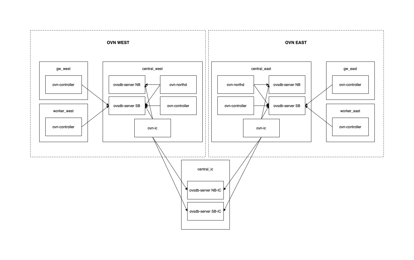
One of the great things of OVN is that North/South routing can happen locally in the hypervisor when a ‘dnat_and_snat‘ rule is used (aka Floating IP) without having to go through a central or network node.

The way it works is that when outgoing traffic reaches the OVN bridge, the source IP address is changed by the Floating IP (snat) and pushed out to the external network. Similarly, when the packet comes in, the Floating IP address is changed (dnat) by that of the virtual machine in the private network.

In the OpenStack world, this is called DVR (“Distributed Virtual Routing”) as the routing doesn’t need to traverse any central node and happens on compute nodes meaning no extra hops, no overlay traffic and distributed routing processing.

The main advantage is that if all your workloads have a Floating IP and a lot of N/S traffic, the cloud can be well dimensioned and it’s very scalable (no need to scale any network/gateway nodes as you scale out the number of computes and less dependency on the control plane). The drawback is that you’ll need to consume IP addresses from the FIP pool. Yeah, it couldn’t be all good news :p

All this introduction to say that during some testing on an OVN cluster with lots of Floating IPs, we noticed that the amount of Logical Flows was *huge* and that led to numerous problems related to a very high CPU and memory consumption on both server (ovsdb-server) and client (ovn-controller) sides.

I wanted to understand how the flows were distributed and what was the main contributor(s) to this explosion. What I did is simply count the number of flows on every stage and sorting them. This showed that 93% of all the Logical Flows were in two stages:

$ head -n 6 logical_flows_distribution_sorted.txt
lr_out_egr_loop: 423414  62.24%
lr_in_ip_routing: 212199  31.19%
lr_in_ip_input: 10831  1.59%
ls_out_acl: 4831  0.71%
ls_in_port_sec_ip: 3471  0.51%
ls_in_l2_lkup: 2360  0.34%

Here’s the simple commands that I used to figure out the flow distribution:

# ovn-sbctl list Logical_Flow > logical_flows.txt

# Retrieve all the stages in the current pipeline
$ grep ^external_ids logical_flows.txt | sed 's/.*stage-name=//' | tr -d '}' | sort | uniq

# Count how many flows on each stage
$ while read stage; do echo $stage: $(grep $stage logical_flows.txt -c); done < stage_names.txt  > logical_flows_distribution.txt

$ sort  -k 2 -g -r logical_flows_distribution.txt  > logical_flows_distribution_sorted.txt

Next step would be to understand what’s in those two tables (lr_out_egr_loop & lr_in_ip_routing):

_uuid               : e1cc600a-fb9c-4968-a124-b0f78ed8139f
actions             : "next;"
external_ids        : {source="ovn-northd.c:8958", stage-name=lr_out_egr_loop}
logical_datapath    : 9cd315f4-1033-4f71-a26e-045a379aebe8
match               : "ip4.src == 172.24.4.10 && ip4.dst == 172.24.4.209"
pipeline            : egress
priority            : 200
table_id            : 2
hash                : 0

_uuid               : c8d8400a-590e-4b7e-b433-7a1491d31488
actions             : "inport = outport; outport = \"\"; flags = 0; flags.loopback = 1; reg9[1] = 1; next(pipeline=ingress, table=0); "
external_ids        : {source="ovn-northd.c:8950", stage-name=lr_out_egr_loop}
logical_datapath    : 9cd315f4-1033-4f71-a26e-045a379aebe8
match               : "is_chassis_resident(\"vm1\") && ip4.src == 172.24.4.218 && ip4.dst == 172.24.4.220"
pipeline            : egress
priority            : 300
table_id            : 2
hash                : 0
_uuid               : 0777b005-0ff0-40cb-8532-f7e2261dae06
actions             : "outport = \"router1-public\"; eth.src = 40:44:00:00:00:06; eth.dst = 40:44:00:00:00:07; reg0 = ip4.dst; reg1 = 172.24.4.218; reg9[2] = 1; reg9[0] = 0; ne
xt;"
external_ids        : {source="ovn-northd.c:6945", stage-name=lr_in_ip_routing}
logical_datapath    : 9cd315f4-1033-4f71-a26e-045a379aebe8
match               : "inport == \"router1-net1\" && ip4.src == 192.168.0.11 && ip4.dst == 172.24.4.226"
pipeline            : ingress
priority            : 400
table_id            : 9
hash                : 0

Turns out that those flows are intended to handle inter-FIP communication. Basically, there are flows for every possible FIP pair so that the traffic doesn’t flow through a Geneve tunnel.

While FIP-to-FIP traffic between two OVN ports is not perhaps the most common use case, those flows are there to handle it that way that the traffic would be distributed and never sent through the overlay network.

A git blame on the code that generates those flows will show the commits [1][2] and some background on the actual issue.

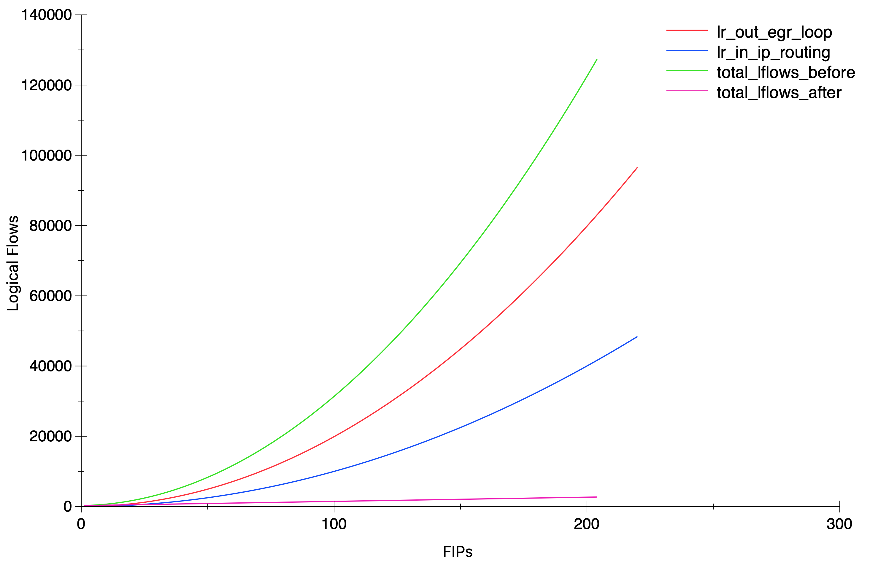
With the results above, one would expect a quadratic growth but still, it’s always nice to pull some graphs 🙂


And again, the simple script that I used to get the numbers in the graph:

ovn-nbctl clear logical_router router1 nat
for i in {1..200}; do
  ovn-nbctl lr-nat-add router1 dnat_and_snat 172.24.4.$i 192.168.0.11 vm1 40:44:00:00:00:07
  # Allow some time to northd to generate the new lflows.
  ovn-sbctl list logical_flow > /dev/null
  ovn-sbctl list logical_flow > /tmp/lflows.txt
  S1=$(grep lr_out_egr_loop -c /tmp/lflows.txt )
  S2=$(grep lr_in_ip_routing -c /tmp/lflows.txt )
  echo $S1 $S2
done

Soon after I reported this scaling issue with the above findings, my colleague Numan did an amazing job fixing it with this patch. The results are amazing and for the same test scenario with 200 FIPs, the total amount of lflows dropped from ~127K to ~2.7K and most importantly, from an exponential to a linear growth.


Since the Logical Flows are represented in ASCII, they are also quite expensive in processing due to the string parsing, and not very cheap to transmit in the OVSDB protocol. This has been a great leap when it comes to scaling scaling environments with a heavy N/S traffic and lots of Floating IPs.

OVN Cluster Interconnection

A new feature has been recently introduced in OVN that allows multiple clusters to be interconnected at L3 level (here’s a link to the series of patches). This can be useful for scenarios with multiple availability zones (or physical regions) or simply to allow better scaling by having independent control planes yet allowing connectivity between workloads in separate zones.

Simplifying things, logical routers on each cluster can be connected via transit overlay networks. The interconnection layer is responsible for creating the transit switches in the IC database that will become visible to the connected clusters. Each cluster can then connect their logical routers to the transit switches. More information can be found in the ovn-architecture manpage.

I created a vagrant setup to test it out and become a bit familiar with it. All you need to do to recreate it is cloning and running ‘vagrant up‘ inside the ovn-interconnection folder:

https://github.com/danalsan/vagrants/tree/master/ovn-interconnection

This will deploy 7 CentOS machines (300MB of RAM each) with two separate OVN clusters (west & east) and the interconnection services. The layout is described in the image below:

Once the services are up and running, a few resources will be created on each cluster and the interconnection services will be configured with a transit switch between them:

Let’s see, for example, the logical topology of the east availability zone, where the transit switch ts1 is listed along with the port in the west remote zone:

[root@central-east ~]# ovn-nbctl show
switch c850599c-263c-431b-b67f-13f4eab7a2d1 (ts1)
    port lsp-ts1-router_west
        type: remote
        addresses: ["aa:aa:aa:aa:aa:02 169.254.100.2/24"]
    port lsp-ts1-router_east
        type: router
        router-port: lrp-router_east-ts1
switch 8361d0e1-b23e-40a6-bd78-ea79b5717d7b (net_east)
    port net_east-router_east
        type: router
        router-port: router_east-net_east
    port vm1
        addresses: ["40:44:00:00:00:01 192.168.1.11"]
router b27d180d-669c-4ca8-ac95-82a822da2730 (router_east)
    port lrp-router_east-ts1
        mac: "aa:aa:aa:aa:aa:01"
        networks: ["169.254.100.1/24"]
        gateway chassis: [gw_east]
    port router_east-net_east
        mac: "40:44:00:00:00:04"
        networks: ["192.168.1.1/24"]

As for the Southbound database, we can see the gateway port for each router. In this setup I only have one gateway node but, as any other distributed gateway port in OVN, it could be scheduled in multiple nodes providing HA

[root@central-east ~]# ovn-sbctl show
Chassis worker_east
    hostname: worker-east
    Encap geneve
        ip: "192.168.50.100"
        options: {csum="true"}
    Port_Binding vm1
Chassis gw_east
    hostname: gw-east
    Encap geneve
        ip: "192.168.50.102"
        options: {csum="true"}
    Port_Binding cr-lrp-router_east-ts1
Chassis gw_west
    hostname: gw-west
    Encap geneve
        ip: "192.168.50.103"
        options: {csum="true"}
    Port_Binding lsp-ts1-router_west

If we query the interconnection databases, we will see the transit switch in the NB and the gateway ports in each zone:

[root@central-ic ~]# ovn-ic-nbctl show
Transit_Switch ts1

[root@central-ic ~]# ovn-ic-sbctl show
availability-zone east
    gateway gw_east
        hostname: gw-east
        type: geneve
            ip: 192.168.50.102
        port lsp-ts1-router_east
            transit switch: ts1
            address: ["aa:aa:aa:aa:aa:01 169.254.100.1/24"]
availability-zone west
    gateway gw_west
        hostname: gw-west
        type: geneve
            ip: 192.168.50.103
        port lsp-ts1-router_west
            transit switch: ts1
            address: ["aa:aa:aa:aa:aa:02 169.254.100.2/24"]

With this topology, traffic flowing from vm1 to vm2 shall flow from gw-east to gw-west through a Geneve tunnel. If we list the ports in each gateway we should be able to see the tunnel ports. Needless to say, gateways have to be mutually reachable so that the transit overlay network can be established:

[root@gw-west ~]# ovs-vsctl show
6386b867-a3c2-4888-8709-dacd6e2a7ea5
    Bridge br-int
        fail_mode: secure
        Port ovn-gw_eas-0
            Interface ovn-gw_eas-0
                type: geneve
                options: {csum="true", key=flow, remote_ip="192.168.50.102"}

Now, when vm1 pings vm2, the traffic flow should be like:

(vm1) worker_east ==== gw_east ==== gw_west ==== worker_west (vm2).

Let’s see it via ovn-trace tool:

[root@central-east vagrant]# ovn-trace  --ovs --friendly-names --ct=new net_east  'inport == "vm1" && eth.src == 40:44:00:00:00:01 && eth.dst == 40:44:00:00:00:04 && ip4.src == 192.168.1.11 && ip4.dst == 192.168.2.12 && ip.ttl == 64 && icmp4.type == 8'


ingress(dp="net_east", inport="vm1")
...
egress(dp="net_east", inport="vm1", outport="net_east-router_east")
...
ingress(dp="router_east", inport="router_east-net_east")
...
egress(dp="router_east", inport="router_east-net_east", outport="lrp-router_east-ts1")
...
ingress(dp="ts1", inport="lsp-ts1-router_east")
...
egress(dp="ts1", inport="lsp-ts1-router_east", outport="lsp-ts1-router_west")
 9. ls_out_port_sec_l2 (ovn-northd.c:4543): outport == "lsp-ts1-router_west", priority 50, uuid c354da11
    output;
    /* output to "lsp-ts1-router_west", type "remote" */

Now let’s capture Geneve traffic on both gateways while a ping between both VMs is running:

[root@gw-east ~]# tcpdump -i genev_sys_6081 -vvnee icmp
tcpdump: listening on genev_sys_6081, link-type EN10MB (Ethernet), capture size 262144 bytes
10:43:35.355772 aa:aa:aa:aa:aa:01 > aa:aa:aa:aa:aa:02, ethertype IPv4 (0x0800), length 98: (tos 0x0, ttl 63, id 11379, offset 0, flags [DF], proto ICMP (1), length 84)
    192.168.1.11 > 192.168.2.12: ICMP echo request, id 5494, seq 40, length 64
10:43:35.356077 aa:aa:aa:aa:aa:01 > aa:aa:aa:aa:aa:02, ethertype IPv4 (0x0800), length 98: (tos 0x0, ttl 63, id 11379, offset 0, flags [DF], proto ICMP (1), length 84)
    192.168.1.11 > 192.168.2.12: ICMP echo request, id 5494, seq 40, length 64
10:43:35.356442 aa:aa:aa:aa:aa:02 > aa:aa:aa:aa:aa:01, ethertype IPv4 (0x0800), length 98: (tos 0x0, ttl 63, id 42610, offset 0, flags [none], proto ICMP (1), length 84)
    192.168.2.12 > 192.168.1.11: ICMP echo reply, id 5494, seq 40, length 64
10:43:35.356734 40:44:00:00:00:04 > 40:44:00:00:00:01, ethertype IPv4 (0x0800), length 98: (tos 0x0, ttl 62, id 42610, offset 0, flags [none], proto ICMP (1), length 84)
    192.168.2.12 > 192.168.1.11: ICMP echo reply, id 5494, seq 40, length 64


[root@gw-west ~]# tcpdump -i genev_sys_6081 -vvnee icmp
tcpdump: listening on genev_sys_6081, link-type EN10MB (Ethernet), capture size 262144 bytes
10:43:29.169532 aa:aa:aa:aa:aa:01 > aa:aa:aa:aa:aa:02, ethertype IPv4 (0x0800), length 98: (tos 0x0, ttl 63, id 8875, offset 0, flags [DF], proto ICMP (1), length 84)
    192.168.1.11 > 192.168.2.12: ICMP echo request, id 5494, seq 34, length 64
10:43:29.170058 40:44:00:00:00:10 > 40:44:00:00:00:02, ethertype IPv4 (0x0800), length 98: (tos 0x0, ttl 62, id 8875, offset 0, flags [DF], proto ICMP (1), length 84)
    192.168.1.11 > 192.168.2.12: ICMP echo request, id 5494, seq 34, length 64
10:43:29.170308 aa:aa:aa:aa:aa:02 > aa:aa:aa:aa:aa:01, ethertype IPv4 (0x0800), length 98: (tos 0x0, ttl 63, id 38667, offset 0, flags [none], proto ICMP (1), length 84)
    192.168.2.12 > 192.168.1.11: ICMP echo reply, id 5494, seq 34, length 64
10:43:29.170476 aa:aa:aa:aa:aa:02 > aa:aa:aa:aa:aa:01, ethertype IPv4 (0x0800), length 98: (tos 0x0, ttl 63, id 38667, offset 0, flags [none], proto ICMP (1), length 84)
    192.168.2.12 > 192.168.1.11: ICMP echo reply, id 5494, seq 34, length 64

You can observe that the ICMP traffic flows between the transit switch ports (aa:aa:aa:aa:aa:02 <> aa:aa:aa:aa:aa:01) traversing both zones.

Also, as the packet has gone through two routers (router_east and router_west), the TTL at the destination has been decremented twice (from 64 to 62):

[root@worker-west ~]# ip net e vm2 tcpdump -i any icmp -vvne
tcpdump: listening on any, link-type LINUX_SLL (Linux cooked), capture size 262144 bytes
10:49:32.491674  In 40:44:00:00:00:10 ethertype IPv4 (0x0800), length 100: (tos 0x0, ttl 62, id 57504, offset 0, flags [DF], proto ICMP (1), length 84)

This is a really great feature that opens a lot of possibilities for cluster interconnection and scaling. However, it has to be taken into account that it requires another layer of management that handles isolation (multitenancy) and avoids IP overlapping across the connected availability zones.