The goal of this post is to describe how network isolation is typically achieved for both the control and data planes in OpenStack using TripleO. In particular, how all this happens in a virtual setup, using one baremetal node (hypervisor, from now on) to deploy the OpenStack nodes with libvirt. For the purpose of this post, we’ll work with a 3 controllers + 1 compute virtual setup.
(undercloud) [stack@undercloud-0 ~]$ openstack server list
+--------------------------------------+--------------+--------+------------------------+
| ID | Name | Status | Networks |
+--------------------------------------+--------------+--------+------------------------+
| b3bd5157-b3ea-4331-91af-3820c4e12252 | controller-0 | ACTIVE | ctlplane=192.168.24.15 |
| 6f228b08-49a0-4b68-925a-17d06224d5f9 | controller-1 | ACTIVE | ctlplane=192.168.24.37 |
| e5c649b5-c968-4293-a994-04293cb16da1 | controller-2 | ACTIVE | ctlplane=192.168.24.10 |
| 9f15ed23-efb1-4972-b578-7b0da3500053 | compute-0    | ACTIVE | ctlplane=192.168.24.14 |
+--------------------------------------+--------------+--------+------------------------+
The tool used to deploy this setup is Infrared (documentation) which is an easy-to-use wrapper around TripleO. Don’t be scared about the so many layers involved here; the main point is to understand that a physical – and somewhat powerful – server is running an OpenStack cluster formed by:
- 3 virtual controllers that run the OpenStack control plane services (Neutron, Nova, Glance, …)
- 1 virtual compute node that will serve to host the workloads (virtual machines) of the OpenStack cluster
From a Networking perspective (I’ll omit the undercloud for simplicity), things are wired like this:
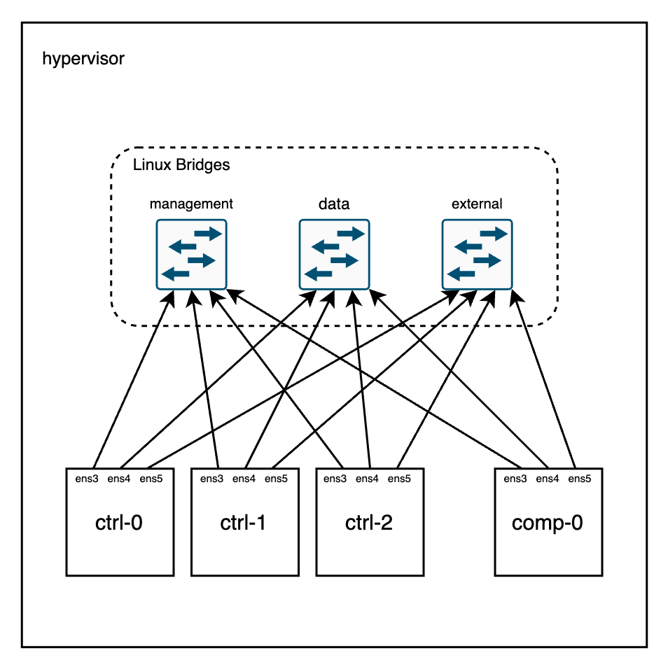 Let’s take a look at the bridges in the hypervisor node:
[root@hypervisor]# brctl show

bridge name     bridge id               STP enabled     interfaces
management      8000.525400cc1d8b       yes             management-nic
                                                        vnet0
                                                        vnet12
                                                        vnet3
                                                        vnet6
                                                        vnet9

external        8000.5254000ceb7c       yes             external-nic
                                                        vnet11
                                                        vnet14
                                                        vnet2
                                                        vnet5
                                                        vnet8

data            8000.5254007bc90a       yes             data-nic
                                                        vnet1
                                                        vnet10
                                                        vnet13
                                                        vnet4
                                                        vnet7
Each bridge has 6 ports (3 controllers, 1 compute, 1 undercloud, and the local port in the hypervisor). Now, each virtual machine running in this node can be mapped to the right interface:
[root@hypervisor]# for i in controller-0 controller-1 controller-2 compute-0; do virsh domiflist $i; done


 Interface   Type      Source       Model    MAC
----------------------------------------------------------------
 vnet9       network   management   virtio   52:54:00:74:29:4f
 vnet10      network   data         virtio   52:54:00:1c:44:26
 vnet11      network   external     virtio   52:54:00:20:3c:4e

 Interface   Type      Source       Model    MAC
----------------------------------------------------------------
 vnet3       network   management   virtio   52:54:00:0b:ad:3b
 vnet4       network   data         virtio   52:54:00:2f:9f:3e
 vnet5       network   external     virtio   52:54:00:75:a5:ed

 Interface   Type      Source       Model    MAC
----------------------------------------------------------------
 vnet6       network   management   virtio   52:54:00:da:a3:1e
 vnet7       network   data         virtio   52:54:00:57:26:67
 vnet8       network   external     virtio   52:54:00:2c:21:d5

 Interface   Type      Source       Model    MAC
----------------------------------------------------------------
 vnet0       network   management   virtio   52:54:00:de:4a:38
 vnet1       network   data         virtio   52:54:00:c7:74:4b
 vnet2       network   external     virtio   52:54:00:22:de:5c
Network configuration templates
This section will go through the Infrared/TripleO configuration to understand how this layout was defined. This will also help the reader to change the CIDRs, VLANs, number of virtual NICs, etc.
First, the deployment script:
$ cat overcloud_deploy.sh
#!/bin/bash

openstack overcloud deploy \
--timeout 100 \
--templates /usr/share/openstack-tripleo-heat-templates \
--stack overcloud \
--libvirt-type kvm \
-e /home/stack/virt/config_lvm.yaml \
-e /usr/share/openstack-tripleo-heat-templates/environments/network-isolation.yaml \
-e /home/stack/virt/network/network-environment.yaml \
-e /home/stack/virt/inject-trust-anchor.yaml \
-e /home/stack/virt/hostnames.yml \
-e /usr/share/openstack-tripleo-heat-templates/environments/services/neutron-ovn-ha.yaml \
-e /home/stack/virt/debug.yaml \
-e /home/stack/virt/nodes_data.yaml \
-e ~/containers-prepare-parameter.yaml \
-e /home/stack/virt/docker-images.yaml \
--log-file overcloud_deployment_99.log
Now, let’s take a look at the network related templates to understand the different networks and how they map to the physical NICs inside the controllers/compute nodes:
$ grep -i -e cidr -e vlan /home/stack/virt/network/network-environment.yaml
ControlPlaneSubnetCidr: '192.168.24.0/24'

ExternalNetCidr: 10.0.0.0/24
ExternalNetworkVlanID: 10

InternalApiNetCidr: 172.17.1.0/24
InternalApiNetworkVlanID: 20

StorageMgmtNetCidr: 172.17.4.0/24
StorageMgmtNetworkVlanID: 40

StorageNetCidr: 172.17.3.0/24
StorageNetworkVlanID: 30

TenantNetCidr: 172.17.2.0/24
TenantNetworkVlanID: 50

NeutronNetworkVLANRanges: tenant:1000:2000

OS::TripleO::Compute::Net::SoftwareConfig: three-nics-vlans/compute.yaml
OS::TripleO::Controller::Net::SoftwareConfig: three-nics-vlans/controller.yaml
In the output above you can see 6 different networks:
- ControlPlane (flat): used mainly for provisioning (PXE) and remote access to the nodes via SSH.
- External (VLAN 10): external network used for dataplane floating IP traffic and access to the OpenStack API services via their external endpoints.
- InternalApi (VLAN 20): network where the OpenStack control plane services will listen for internal communication (eg. Neutron <-> Nova).
- StorageMgmt (VLAN 40): network used to manage the storage (in this deployment, swift-object-server, swift-container-server, and swift-account-server will listen to requests on this network)
- Storage (VLAN 30): network used for access to the Object storage (in this deployment, swift-proxy will listen to requests on this network).
- Tenant: this network will carry the overlay tunnelled traffic (Geneve for OVN, VXLAN in the case of ML2/OVS) in the VLAN 50 but will also carry dataplane traffic if VLAN tenant networks are used in Neutron. The VLAN range allowed for such traffic is specified also in the template (in the example, VLAN ids ranging from 1000-2000 are reserved for Neutron tenant networks).
The way that each NIC is mapped to each network is defined in the yaml files below. For this deployment, I used a customized layout via this patch (controller.yaml and compute.yaml). Essentially, the mapping looks like this:
- Controllers:
- nic1: ControlPlaneIp (flat); InternalApi (20), Storage (30) , StorageMgmt (40), VLAN devices
- nic2: br-tenant OVS bridge and VLAN50 for the tunnelled traffic
- nic3: br-ex OVS bridge for external traffic
- Compute:
- nic1: ControlPlaneIp (flat); InternalApi (20), Storage (30), VLAN devices
- nic2: br-tenant OVS bridge and VLAN50 for the tunnelled traffic
- nic3: br-ex OVS bridge for external traffic
The nodes map nic1, nic2, nic3 to ens4, ens5, ens6 respectively:
[root@controller-0 ~]# ip l | egrep "vlan[2-4]0"
9: vlan20@ens3: <BROADCAST,MULTICAST,UP,LOWER_UP> mtu 1500 qdisc noqueue state UP mode DEFAULT group default qlen 1000
10: vlan30@ens3: <BROADCAST,MULTICAST,UP,LOWER_UP> mtu 1500 qdisc noqueue state UP mode DEFAULT group default qlen 1000
11: vlan40@ens3: <BROADCAST,MULTICAST,UP,LOWER_UP> mtu 1500 qdisc noqueue state UP mode DEFAULT group default qlen 1000

[root@controller-0 ~]# ovs-vsctl list-ports br-tenant
ens4
vlan50

[root@controller-0 ~]# ovs-vsctl list-ports br-ex
ens5
In the controller nodes we’ll find an haproxy instance load balancing the requests to the different nodes and we can see here the network layout as well:
[root@controller-1 ~]# podman exec -uroot -it haproxy-bundle-podman-1 cat /etc/haproxy/haproxy.cfg

listen neutron
  bind 10.0.0.122:9696 transparent      <--- External network
  bind 172.17.1.48:9696 transparent     <--- InternalApi network
  mode http
  http-request set-header X-Forwarded-Proto https if { ssl_fc }
  http-request set-header X-Forwarded-Proto http if !{ ssl_fc }
  http-request set-header X-Forwarded-Port %[dst_port]
  option httpchk
  option httplog
# Now the backends in the InternalApi network
  server controller-0.internalapi.local 172.17.1.72:9696 check fall 5 inter 2000 rise 2
  server controller-1.internalapi.local 172.17.1.101:9696 check fall 5 inter 2000 rise 2
  server controller-2.internalapi.local 172.17.1.115:9696 check fall 5 inter 2000 rise 2
In the above output, the IP address 172.17.1.48 is a virtual IP managed by pacemaker and will live in the InternalApi (VLAN 20) network where it is master:
[root@controller-1 ~]# pcs status | grep 172.17.1.48
  * ip-172.17.1.48      (ocf::heartbeat:IPaddr2):       Started controller-0

[root@controller-0 ~]# ip a |grep 172.17.1.48
    inet 172.17.1.48/32 brd 172.17.1.255 scope global vlan20
Traffic inspection
With a clear view on the networking layout, now we can use the hypervisor to hook a tcpdump in the right bridge and check for whatever traffic we’re interested in.
Let’s for example ping from the InternalApi (172.17.1.0/24) network on controller-0 to controller-1 and check the traffic in the hypervisor:
[heat-admin@controller-0 ~]$ ping controller-1.internalapi.local
PING controller-1.internalapi.redhat.local (172.17.1.101) 56(84) bytes of data.
64 bytes from controller-1.redhat.local (172.17.1.101): icmp_seq=1 ttl=64 time=0.213 ms
64 bytes from controller-1.redhat.local (172.17.1.101): icmp_seq=2 ttl=64 time=0.096 ms


[root@hypervisor]# tcpdump -i management -vvne icmp -c2
tcpdump: listening on management, link-type EN10MB (Ethernet), capture size 262144 bytes
15:19:08.418046 52:54:00:74:29:4f > 52:54:00:0b:ad:3b, ethertype 802.1Q (0x8100), length 102: vlan 20, p 0, ethertype IPv4, (tos 0x0, ttl 64, id 58494, offset 0, flags [DF], proto ICMP (1), length 84)

    172.17.1.72 > 172.17.1.101: ICMP echo request, id 53086, seq 5, length 64
15:19:08.418155 52:54:00:0b:ad:3b > 52:54:00:74:29:4f, ethertype 802.1Q (0x8100), length 102: vlan 20, p 0, ethertype IPv4, (tos 0x0, ttl 64, id 39897, offset 0, flags [none], proto ICMP (1), length 84)
    172.17.1.101 > 172.17.1.72: ICMP echo reply, id 53086, seq 5, length 64


[root@hypervisor]# brctl showmacs management | egrep "52:54:00:0b:ad:3b|52:54:00:74:29:4f"
port no mac addr                is local?       ageing timer
  3     52:54:00:0b:ad:3b       no                 0.01
  5     52:54:00:74:29:4f       no                 0.01
When we ping to the controller-1 IP address of the InternalApi network, the traffic is tagged (VLAN 20) and going through the management bridge in the hypervisor. This matches our expectations as we defined such network in the template files that way.
Similarly, we could trace more complicated scenarios like an OpenStack instance in a tenant network pinging an external destination:
(overcloud) [stack@undercloud-0 ~]$ openstack server list
+--------------------------------------+---------+--------+-----------------------+--------+
| ID | Name | Status | Networks | Image |
+--------------------------------------+---------+--------+-----------------------+--------+
| 3d9f6957-5311-4590-8c62-097b576ffa04 | cirros1 | ACTIVE | private=192.168.0.166 | cirros |
+--------------------------------------+---------+--------+-----------------------+--------+


[root@compute-0 ~]# sudo ip net e ovnmeta-e49cc182-247c-4dc9-9589-4df6fcb09511 ssh cirros@192.168.0.166
cirros@192.168.0.166's password:
$ ping 8.8.8.8
PING 8.8.8.8 (8.8.8.8): 56 data bytes
64 bytes from 8.8.8.8: seq=0 ttl=53 time=10.356 ms
64 bytes from 8.8.8.8: seq=1 ttl=53 time=8.591 ms
Now in the hypervisor, we’ll trace the Geneve traffic (VLAN50):
# tcpdump -i data -vvnne vlan 50 and "(udp port 6081) and (udp[10:2] = 0x6558) and (udp[(8 + (4 * (2 + (udp[8:1] & 0x3f))) + 12):2] = 0x0800) and (udp[8 + (4 * (2 + (udp[8:1] & 0x3f))) + 14 + 9:1] = 01)"  -c2

tcpdump: listening on data, link-type EN10MB (Ethernet), capture size 262144 bytes

16:21:28.642671 6a:9b:72:22:3f:68 > 0e:d0:eb:00:1b:e7, ethertype 802.1Q (0x8100), length 160: vlan 50, p 0, ethertype IPv4, (tos 0x0, ttl 64, id 15872, offset 0, flags [DF], proto UDP (17), length 142)
    172.17.2.119.27073 > 172.17.2.143.6081: [bad udp cksum 0x5db4 -> 0x1e8c!] Geneve, Flags [C], vni 0x5, proto TEB (0x6558), options [class Open Virtual Networking (OVN) (0x102) type 0x80(C) len 8 data 00010003]
        fa:16:3e:a7:95:87 > 52:54:00:0c:eb:7c, ethertype IPv4 (0x0800), length 98: (tos 0x0, ttl 63, id 50335, offset 0, flags [DF], proto ICMP (1), length 84)
    192.168.0.166 > 8.8.8.8: ICMP echo request, id 2818, seq 2145, length 64


16:21:28.650412 0e:d0:eb:00:1b:e7 > 6a:9b:72:22:3f:68, ethertype 802.1Q (0x8100), length 160: vlan 50, p 0, ethertype IPv4, (tos 0x0, ttl 64, id 26871, offset 0, flags [DF], proto UDP (17), length 142)
    172.17.2.143.31003 > 172.17.2.119.6081: [bad udp cksum 0x5db4 -> 0x4a04!] Geneve, Flags [C], vni 0x3, proto TEB (0x6558), options [class Open Virtual Networking (OVN) (0x102) type 0x80(C) len 8 data 00040002]
        fa:16:3e:34:a2:0e > fa:16:3e:63:c0:7a, ethertype IPv4 (0x0800), length 98: (tos 0x0, ttl 53, id 0, offset 0, flags [none], proto ICMP (1), length 84)
    8.8.8.8 > 192.168.0.166: ICMP echo reply, id 2818, seq 2145, length 64
(First, sorry for the complicated filter; I picked it up from here and adapted it to match on the inner protocol of the Geneve traffic against ICMP. If there’s an easier way please tell me :p)
We can see that the Geneve traffic goes between 6a:9b:72:22:3f:68 and 0e:d0:eb:00:1b:e7 and now we can determine the source/dest nodes:
[root@hypervisor]# brctl showmacs data
  2     6a:9b:72:22:3f:68       no                 0.32
  2     fe:54:00:c7:74:4b       yes                0.00
  2     fe:54:00:c7:74:4b       yes                0.00
  3     0e:d0:eb:00:1b:e7       no                 0.40
  3     fe:54:00:2f:9f:3e       yes                0.00
  3     fe:54:00:2f:9f:3e       yes                0.00
From the info above we can see that port 2 corresponds to the MAC ending in “74:4b” and port 3 corresponds to the MAC ending in “9f:3e“. Therefore, this Geneve traffic is flowing from the compute-0 node to the controller-1 node which is where Neutron is running the gateway to do the SNAT towards the external network. Now, this last portion can be examined in the external bridge:
[root@hypervisor]# tcpdump -i external icmp -vvnnee -c2
tcpdump: listening on external, link-type EN10MB (Ethernet), capture size 262144 bytes

16:33:35.016198 fa:16:3e:a7:95:87 > 52:54:00:0c:eb:7c, ethertype IPv4 (0x0800), length 98: (tos 0x0, ttl 63, id 13537, offset 0, flags [DF], proto ICMP (1), length 84)
    10.0.0.225 > 8.8.8.8: ICMP echo request, id 4354, seq 556, length 64

16:33:35.023570 52:54:00:0c:eb:7c > fa:16:3e:a7:95:87, ethertype IPv4 (0x0800), length 98: (tos 0x0, ttl 54, id 0, offset 0, flags [none], proto ICMP (1), length 84)
    8.8.8.8 > 10.0.0.225: ICMP echo reply, id 4354, seq 556, length 64
In case that you’re wondering what’s 10.0.0.225; that’s the IP address of the Neutron gateway:
(overcloud) [stack@undercloud-0 ~]$ openstack router show router1 | grep gateway
| external_gateway_info   | {"network_id": "fe8330fe-540a-4acf-bda8-394398fb4272", "external_fixed_ips": [{"subnet_id": "e388a080-1953-4cdd-9e35-48d416fe2ae1", "ip_address": "10.0.0.225"}
Similarly, the MAC addresses can be matched to confirm that the traffic goes from the gateway node (controller-1), as the MAC ending in “a5:ed” – in the same port as the source MAC from the ICMP packet – corresponds to the NIC attached to the external network on the controller-1.
[root@hypervisor]# brctl showmacs external
  3     fa:16:3e:a7:95:87       no                 0.47
  3     fe:54:00:75:a5:ed       yes                0.00
  3     fe:54:00:75:a5:ed       yes                0.00
Reflection
This is a virtual setup and everything is confined to the boundaries of a physical server. However, it is a great playground to get yourself familiar with the underlay networking of an OpenStack setup (and networking in general ;). Once you get your hands on a real production environment, all these Linux bridges will be replaced by ToR switches (or even routers on a pure L3 Spine & Leaf architecture) but the fundamentals are the same.