In this tutorial I will explain how to solve a crackme rated level 4 at crackmes.de from DrSpliff which I found very interesting.
You can download the original author’s file from here.
You can download both the original file and the patched one created by me from here.
The readme file says:
This crackme uses the basic principals and building blocks of software protection on Unix systems with a little bit of crypto thrown in to piss you off.
Difficulty: 4 – Needs special knowledge
Platform: Unix/linux etc.
Language: C/C++
_________________
Actually this is not a Linux dependent crackme since it’s got no specific Unix/Linux protections but it was compiled for it though.
First thing we do is executing the binary (although I trust crackmes.de I use to have a quick look at the binaries to avoid malicious code being executed on my machine).
daniel@gargamel:~/crackme$ ./drscm1

Dr.Spliff's Crackme - v0.1 (Alpha) (Linux/ia32)

Name: daniel

Serial: 123

Sorry daniel, your license is invalid
Having a quick look at the binary and loading it into gdb it seems that the author’s not used any antidebugging techniques nor ELF header corruption so we can freely analyze / disassemble it.
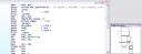 First I opened it with IDA (my favourite disassembler. It’s for Windows but you can run it under wine) to analyze the program flow with its nice Graph View. Quickly I can see where in the code it reads our name / serial (see image).
After this, some memory is allocated via malloc and a buffer is copied into it. This buffer is 56 bytes long and it’s located at address 0x8049a20 (this may change in your computer). After the copy, this buffer is modified somehow by this piece of code:
At the beggining of the loop, edi is pointing to our buffer and it’s being processed in blocks of 8 bytes (64 bits).
.text:08048742                 push    edi
.text:08048743                 add     edi, 8
.text:08048746                 push    offset 08049A5C
.text:0804874B                 call    sub_080485AF
.text:08048750                 add     [ebp+var_410], 8
.text:08048757                 pop     eax
.text:08048758                 pop     edx
.text:08048759                 movsx   eax, byte_8049A58
.text:08048760                 cmp     [ebp+var_410], eax
.text:08048766                 jl      short loc_8048742
If we look further into sub_080485AF, we can identify its main loop with a ‘suspicious’ structure:
.text:080485DB                 mov     edx, ecx
.text:080485DD                 lea     eax, [esi+ecx]
.text:080485E0                 shl     edx, 4
.text:080485E3                 add     edx, [ebp+var_14]
.text:080485E6                 xor     edx, eax
.text:080485E8                 mov     eax, ecx
.text:080485EA                 shr     eax, 5
.text:080485ED                 add     eax, [ebp+var_18]
.text:080485F0                 xor     edx, eax
.text:080485F2                 sub     ebx, edx
.text:080485F4                 mov     edx, ebx
.text:080485F6                 shl     edx, 4
.text:080485F9                 lea     eax, [esi+ebx]
.text:080485FC                 add     edx, [edi]
.text:080485FE                 add     esi, 61C88647h
.text:08048604                 xor     edx, eax
.text:08048606                 mov     eax, ebx
.text:08048608                 shr     eax, 5
.text:0804860B                 add     eax, [edi+4]
.text:0804860E                 xor     edx, eax
.text:08048610                 sub     ecx, edx
.text:08048612                 dec     [ebp+var_10]
.text:08048615                 jns     short loc_80485DB
Notice the 4-bit shifts to the left and the 5-bit shifts to the right. It looks familiar… hmm, maybe TEA? That’s it! Having a look at a public implementation of TEA algorithm we can say for sure it is and this is actually the decoding function. If this is the decoding function, the key used shouldn’t be too far away and the stack is a good place to look at first. Indeed, it’s there and it looks like it’s been hardcoded by the author (at least there are no x-refs to it).
Okay, let’s go along the code and see what happens after all this crypto stuff. We find this piece of code:
.text:08048768                 push    0               ; prot
.text:0804876A                 movsx   eax, byte_8049A58
.text:08048771                 push    eax             ; len
.text:08048772                 push    ds:addr         ; addr
.text:08048778                 call    _mprotect
.text:0804877D                 push    offset sub_804855B
.text:08048782                 push    offset sub_80484FC
.text:08048787                 push    ebx
.text:08048788                 call    ds:addr
Interesting huh? The address at ‘ds:addr’ is actually our decrypted buffer. The mprotect function call is used to set protection of a memory mapping and as we can see in the code above the protection argument is zero or (PROT_NONE) to allow execution of the memory which is about to be executed in the ‘call ds:addr’ instruction.
The arguments of the function which is supposed to be in ‘ds:addr’ are two procedures: sub_804855B and sub_80484FC. Clearly these procedures are the ‘bad and good’ boys. I could try to change the code so that the good boy address is pushed twice onto the stack but the function at ‘ds:addr’ could check that the two parameters are distinct and this wouldn’t be a real crack 🙂 I’d like to dig more into the executable to find out what the author really pretended.
So, the way to go is to load the executable with GDB and break just after the data is already decrypted so that we can analyze what it really holds:
 (gdb) x/56i *0x8049b8c
0x804a028:      push   %ebp
0x804a029:      mov    %esp,%ebp
0x804a02b:      push   %esi
0x804a02c:      sub    $0x4,%esp
0x804a02f:      mov    0x8(%ebp),%esi      ; take a ptr to a ptr to the name
0x804a032:      mov    $0x0,%ecx           ; ecx = 0
0x804a037:      mov    (%esi),%edx         ; edx = ptr to the name
0x804a039:      cmpb   $0x0,(%edx)         ; compare ''
0x804a03c:      je     0x804a049           ; if string's finished jump to 0x804a049
loop:
0x804a03e:      movsbl (%edx),%eax         ; eax = name[i]
0x804a041:      add    %eax,%ecx           ; ecx += name[i]
0x804a043:      inc    %edx                ; ptr++
0x804a044:      cmpb   $0x0,(%edx)         ; name[i] == '' ?
0x804a047:      jne    0x804a03e           ; no -> jump to loop
0x804a049:      cmp    0x4(%esi),%ecx      ; compare with the serial when string's fully proccessed
end_loop:
0x804a04c:      jne    0x804a057           ; if we nop this jump, then we'll always have the goodboy
0x804a04e:      sub    $0xc,%esp
0x804a051:      push   %esi
0x804a052:      call   *0xc(%ebp)          ; call good boy
0x804a055:      nop
0x804a056:      nop
0x804a057:      sub    $0xc,%esp
0x804a05a:      push   %esi
0x804a05b:      call   *0x10(%ebp)         ; call bad boy
0x804a05e:      nop
0x804a05f:      nop
The good boy is at ebp+0x0C and the bad boy at ebp+0x10C. The routine performs a simple algorithm and then compares the result to the serial we entered. If they match, then we’ll have the good boy. We can see that writing a keygen is pretty easy now and that’s why I won’t do it.
So, by simply nopping the ‘jne 0x804a057’ instruction located at 0x804a04c we’ll get the application to show the good boy no matter whether the serial is right or not. To do this we have to dump these 56 bytes, patch and re-cypher them using TEA with the same key.
Key used by the executable for decryption:
TEA_Key
db 75h, 8, 0D3h, 16h, 0D1h, 3, 0Eh, 0 ; 0
db 0E5h, 2Bh, 96h, 0, 8Fh, 45h, 1Eh, 0 ; 8
TEA cyphered data:
.data:08049A20 db 0Ch, 26h, 0F5h, 42h, 0A3h, 0ACh, 0D3h, 3Ch; 0
.data:08049A20 db 0DCh, 0B3h, 86h, 0B2h, 4Bh, 0C5h, 3Ch, 29h; 8
.data:08049A20 db 88h, 66h, 49h, 73h, 0A4h, 0CFh, 7Bh, 0B1h; 16
.data:08049A20 db 3Ah, 5Bh, 0CBh, 37h, 0BDh, 2Ah, 35h, 0FCh; 24
.data:08049A20 db 95h, 0E7h, 0E8h, 0BAh, 2Bh, 66h, 67h, 0BCh; 32
.data:08049A20 db 2Dh, 0AFh, 34h, 32h, 2Eh, 5Bh, 0C1h, 0Eh; 40
.data:08049A20 db 1Eh, 0FAh, 8Eh, 63h, 6Dh, 0C1h, 51h, 78h; 48
Putting this all together we need a TEA implementation. I will use the following source code:
void code(long *v, long *k)

{   unsigned long y = v[0],
                  z = v[1],
                  sum = 0,		/* set up */
                  delta = 0x9e3779b9,
                  n = 32,
                  a = k[0],
                  b = k[1],
                  c = k[2],
                  d = k[3];
while (n-- > 0)			/* basic cycle start */
    {   sum += delta;
        y   += (z <> 5) + b;
        z   += (y <> 5) + d;		/* end cycle */
    }
v[0] = y;
    v[1] = z;
}
void decode(long *v, long *k)
{   unsigned long n = 32,
                  sum,
                  y = v[0],
                  z = v[1],
                  delta = 0x9e3779b9,
                  a = k[0],
                  b = k[1],
                  c = k[2],
                  d = k[3];
sum = delta < 0)
    {   z   -= (y <> 5) + d;
        y   -= (z <> 5) + b;
        sum -= delta;
    }
 					/* end cycle */
    v[0] = y;
    v[1] = z;
}
int main(int argc, char **argv)
{
long cyphered[] = {0x42F5260C, 0x3CD3ACA3, 0x0B286B3DC, 0x293CC54B, 0x73496688, 0x0B17BCFA4, 0x37CB5B3A, 0x0FC352ABD, 0x0BAE8E795, 0x0BC67662B, 0x3234AF2D, 0x0EC15B2E, 0x638EFA1E, 0x7851C16D };
long key[] = {  0x16D30875, 0x0E03D1, 0x962BE5, 0x1E458F };
long *ptrc;
int i;
ptrc=cyphered;
 for(i=0;i<7;i++)
 {
 	decode((unsigned long *)ptrc, (unsigned long *)key);
 	ptrc+=2;
 }
 return 1;
}
Executing this code we will get our buffer decrypted (we could have got this data by debugging the executable itself but this way we are also checking that everything is going all right). Having a look at the ‘cyphered’ buffer with gdb on the above program:
(gdb) p/x cyphered
{0x56e58955, 0x8b04ec83, 0xb90875, 0x8b000000,
0x3a8016, 0xbe0f0b74, 0x42c10102, 0x75003a80,
0x44e3bf5, 0xec830975, 0x55ff560c, 0x8390900c,
0xff560cec, 0x90901055}
Okay here is the decyphered buffer with actually holds the code executed by our binary. It contains the jnz to be nopped by us so we can clearly identify the JNZ opcodes (0x0975) which should be changed by two NOP’s (0x9090) and the buffer would look like this:
{0x56e58955, 0x8b04ec83, 0xb90875, 0x8b000000,
0x3a8016, 0xbe0f0b74, 0x42c10102, 0x75003a80,
0x44e3bf5, 0xec839090, 0x55ff560c, 0x8390900c,
0xff560cec, 0x90901055}
So now it’s time to cypher this data using the same key so that when our program decrypts it, we always get the good boy.
int main(int argc, char **argv)
{long decyphered[] = {	0x56e58955, 0x8b04ec83, 0xb90875, 0x8b000000,0x3a8016, 0xbe0f0b74, 0x42c10102, 0x75003a80,0x44e3bf5, 0xec839090, 0x55ff560c, 0x8390900c,0xff560cec, 0x90901055 };
long key[] = {  0x16D30875, 0x0E03D1, 0x962BE5, 0x1E458F };
long *ptrd;
char *ptr;
int i;
ptrd=decyphered;
 for(i=0;i<7;i++)
 {
 	code((unsigned long *)ptrd, (unsigned long *)key);
 	ptrd+=2;
 }
ptr=(char*)decyphered;
 for(i=0;i<56;i++)
 	printf("%02X,",ptr[i]);
return 1;
}
The output of this program:
0x0C, 0x26, 0xF5, 0x42, 0xA3, 0xAC, 0xD3, 0x3C,
0xDC, 0xB3, 0x86, 0xB2, 0x4B, 0xC5, 0x3C, 0x29,
0x88, 0x66, 0x49, 0x73, 0xA4, 0xCF, 0x7B, 0xB1,
0x3A, 0x5B, 0xCB, 0x37, 0xBD, 0x2A, 0x35, 0xFC,
0x05, 0x51, 0x3F, 0xE3, 0xCF, 0x7F, 0x2D, 0x78,
0x2D, 0xAF, 0x34, 0x32, 0x2E, 0x5B, 0xC1, 0x0E,
0x1E, 0xFA, 0x8E, 0x63, 0x6D, 0xC1, 0x51, 0x78,
Actually the only block (8 bytes long) which has changed’s been obviously the one containing the NOP’ed JNZ so its bytes are to be substituted in the original binary file. We open it with our favourite hex-editor and patch the file.
Once we’ve patched the file it’s time to try and see what’s going on after all this job:
daniel@gargamel:~/crackme$ ./drscm1-patched

Dr.Spliff's Crackme - v0.1 (Alpha) (Linux/ia32)

Name: daniel

Serial: 123

Congrats daniel, your license is valid

Now, go post your solution on crackmes.de so others can learn
daniel@gargamel:~/crackme$ ./drscm1-patched

Dr.Spliff's Crackme - v0.1 (Alpha) (Linux/ia32)

Name: dani

Serial: 4535

Congrats dani, your license is valid

Now, go post your solution on crackmes.de so others can learn
daniel@gargamel:~/crackme$ ./drscm1-patched

Dr.Spliff's Crackme - v0.1 (Alpha) (Linux/ia32)

Name: aa

Serial: 194

Congrats aa, your license is valid
Great ! It worked! Now let’s have a look at the modified code to see how it looks like after the patch:
(gdb) x/24i 0x804a028
0x804a028:      push   %ebp
0x804a029:      mov    %esp,%ebp
0x804a02b:      push   %esi
0x804a02c:      sub    $0x4,%esp
0x804a02f:      mov    0x8(%ebp),%esi
0x804a032:      mov    $0x0,%ecx
0x804a037:      mov    (%esi),%edx
0x804a039:      cmpb   $0x0,(%edx)
0x804a03c:      je     0x804a049
0x804a03e:      movsbl (%edx),%eax
0x804a041:      add    %eax,%ecx
0x804a043:      inc    %edx
0x804a044:      cmpb   $0x0,(%edx)
0x804a047:      jne    0x804a03e
0x804a049:      cmp    0x4(%esi),%ecx
0x804a04c:      nop    			<---- Our NOP-ed JNZ
0x804a04d:      nop    			<---- Our NOP-ed JNZ
0x804a04e:      sub    $0xc,%esp
0x804a051:      push   %esi
0x804a052:      call   *0xc(%ebp)	<---- Always call the good boy
0x804a055:      nop
This is the hardest part of the crackme. However we assumed for simplicity that the serial entered is a number. However the program checks the return of an atoi() call to the serial. If atoi fails then the ‘Invalid serial’ message appears. To avoid this, just patch the jne after the atoi call and replace it by an unconditional jump:
80486d8: jne 0x80486f8
Open the file with an hexeditor and change the 0x75 (JNE opcode) byte at 0x6d8 by a 0xEB (JMP opcode).
Also, the program performs a check to the length of the input name:
or      edx, 0FFFFFFFFh
xor     eax, eax
cld
mov     ecx, edx
repne scasb
not     ecx
dec     ecx
cmp     ecx, 1
ja      short loc_804869A
This is a typical ‘strlen’ and the jump to 0x804869A is taken just if the length of the name is > 0.
So if we want to skip this restriction, we could patch the JA opcode the same way: Replacing the 0x77 (JA) byte at 0x68C offset of the file by a 0xEB (JMP).
The End.
Hope you enjoyed this article and found it useful.
Regards,
Daniel