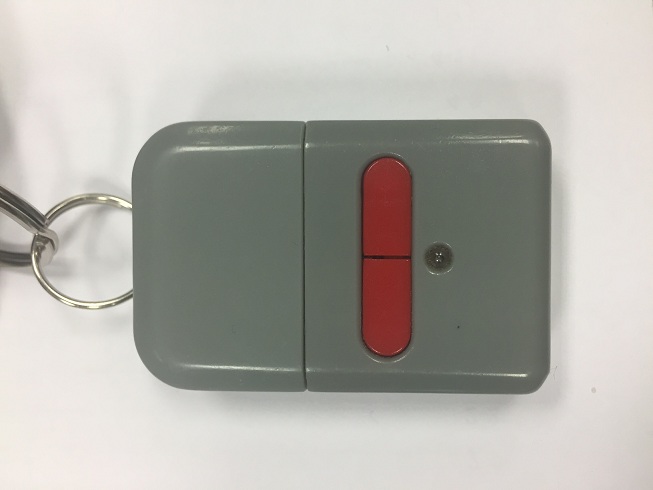
A new cool gadget has fallen into my hands: a SDR DVB-T dongle based on the Realtek RTL2832U chipset. Little did I know I was gonna get so fascinated about this world and first thing I wanted to try is to open my garage door from an Arduino as a “Hello World” exercise.
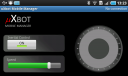
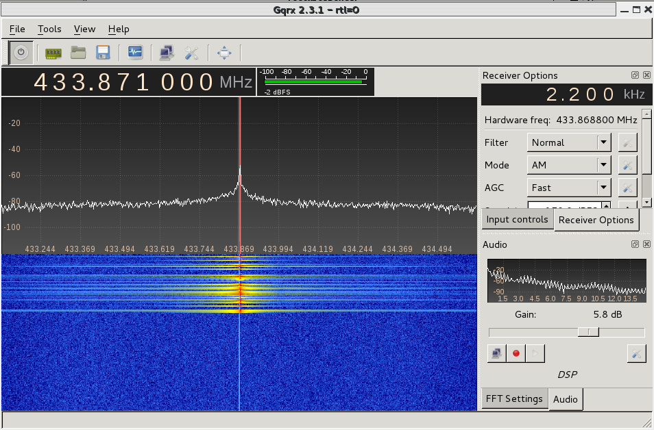
Firstly, I installed the necessary software on a Kali Linux distribution and checked the frequency of the remote with the gqrx tool:
Then, I dumped the signal for further analysis into a wav file using the gnuradio-companion software:

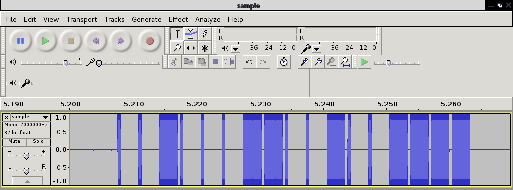
This flowgraph will let us sample the signal sent by the remote and write it into a Wav file. After pressing the buttons on the remote we can see how it looks like in Audacity:

The modulation used by the remote is OOK and looks like it uses Manchester codification. Using the rtl_433 tool, I was able to decode the frame and correlate it with the waveform above:
*** signal_start = 2189802, signal_end = 2300238
signal_len = 110436,  pulses = 86
Iteration 1. t: 404    min: 110 (47)    max: 699 (39)    delta 241
Iteration 2. t: 404    min: 110 (47)    max: 699 (39)    delta 0
Pulse coding: Short pulse length 110 - Long pulse length 699

Short distance: 83, long distance: 675, packet distance: 4804

p_limit: 404
bitbuffer:: Number of rows: 6
[00] {4} f0 : 1111
[01] {18} 23 23 c0 : 00100011 00100011 11
[02] {18} 23 23 c0 : 00100011 00100011 11
[03] {18} 23 23 c0 : 00100011 00100011 11
[04] {18} 23 23 c0 : 00100011 00100011 11
[05] {10} 23 00 : 00100011 00
As long as the button’s pressed, the remote will keep on transmitting the 18-bit frame which we have identified as: 00100011 00100011 11. This bitstream can be clearly seen on Audacity.
From the output above, the short pulses got 110 counts and the long pulses 699. Since the rtl_433 tool samples at 250KHz, it means that they last 440us while the long ones last 2800us. All we need to do now is write the software for the Arduino board to replicate the signal:
#define rfTransmitPin 4
#define ledPin 13
#define buttonPin 9

void setup(){

	pinMode(rfTransmitPin, OUTPUT);
	pinMode(ledPin, OUTPUT);
	pinMode(botonPin, INPUT);

	digitalWrite(rfTransmitPin, LOW);
 }

  void loop(){
    if(digitalRead(buttonPin) == HIGH)   // if the button is pressed, tx the code
      transmitCode();
  }

#define SHORT_WAIT	delayMicroseconds(440)
#define LONG_WAIT	delayMicroseconds(2800)
#define TX_LOW		digitalWrite(rfTransmitPin, LOW)
#define TX_HIGH		digitalWrite(rfTransmitPin, HIGH)
#define OUTPUT_0	{TX_HIGH; SHORT_WAIT; TX_LOW; LONG_WAIT;}
#define OUTPUT_1	{TX_HIGH; LONG_WAIT;  TX_LOW; SHORT_WAIT;}

#define FRAME_SIZE        18

unsigned char code[] = {0,0,1,0,0,0,1,1,0,0,1,0,0,0,1,1,1,1};

void transmitCode() {

    digitalWrite(ledPin, HIGH);

	for(int i=0;i<CODE_SIZE;i++)
	{
		if(code_left[i] == 1)
		{
			OUTPUT_1;
		}
		else
		{
			OUTPUT_0;
		}
	}
	digitalWrite(rfTransmitPin, LOW);
	delay(200);

    digitalWrite(ledPin, LOW);
 }
Now, let’s download it into the microcontroller and capture what it’s sent to see if it matches the original code:
The waveform looks pretty much the same as the one sent by the remote. Also, the rtl_433 tool is able to decode it properly and the timing looks quite nice too:
*** signal_start = 12434285, signal_end = 12748315
signal_len = 314030,  pulses = 144
Iteration 1. t: 413    min: 115 (84)    max: 711 (60)    delta 8
Iteration 2. t: 413    min: 115 (84)    max: 711 (60)    delta 0
Pulse coding: Short pulse length 115 - Long pulse length 711
Short distance: 112, long distance: 708, packet distance: 25527

p_limit: 413
bitbuffer:: Number of rows: 8
[00] {18} 23 23 c0 : 00100011 00100011 11
[01] {18} 23 23 c0 : 00100011 00100011 11
[02] {18} 23 23 c0 : 00100011 00100011 11
[03] {18} 23 23 c0 : 00100011 00100011 11
[04] {18} 23 23 c0 : 00100011 00100011 11
[05] {18} 23 23 c0 : 00100011 00100011 11
[06] {18} 23 23 c0 : 00100011 00100011 11
[07] {18} 23 23 c0 : 00100011 00100011 11
Now we’re sure that the Arduino board will transmit the same signal, it’s time to try it by the garage door and… it WORKS! 🙂
It is a very simple project but as a first contact with the RTL-SDR world I had a lot of fun. I’m looking forward to learning more about it, especially the gnuradio-companion software for signal processing and analysis.