Author: dani

Multinode OVN setup

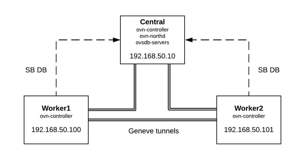
As a follow up from the last post, we are now going to deploy a 3 nodes OVN setup to demonstrate basic L2 communication across different hypervisors. This is the physical topology and how services are distributed:

  • Central node: ovn-northd and ovsdb-servers (North and Southbound databases) as well as ovn-controller
  • Worker1 / Worker2: ovn-controller connected to Central node Southbound ovsdb-server (TCP port 6642)

In order to deploy the 3 machines, I’m using Vagrant + libvirt and you can checkout the Vagrant files and scripts used from this link. After running ‘vagrant up’, we’ll have 3 nodes with OVS/OVN installed from sources and we should be able to log in to the central node and verify that OVN is up and running and Geneve tunnels have been established to both workers:


[vagrant@central ~]$ sudo ovs-vsctl show
f38658f5-4438-4917-8b51-3bb30146877a
    Bridge br-int
        fail_mode: secure
        Port br-int
            Interface br-int
                type: internal
        Port "ovn-worker-1"
            Interface "ovn-worker-1"
                type: geneve
                options: {csum="true", key=flow, remote_ip="192.168.50.101"}
        Port "ovn-worker-0"
            Interface "ovn-worker-0"
                type: geneve
                options: {csum="true", key=flow, remote_ip="192.168.50.100"}
    ovs_version: "2.11.90"


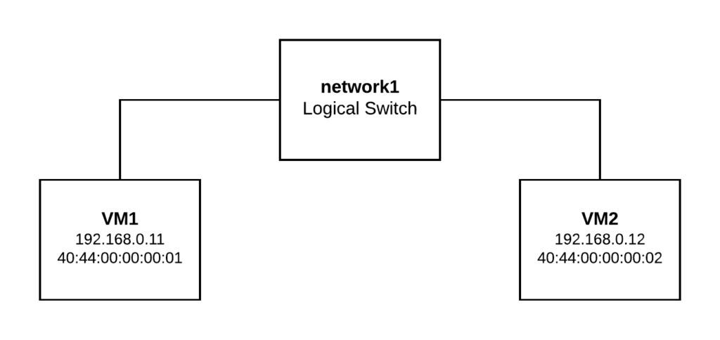
For demonstration purposes, we’re going to create a Logical Switch (network1) and two Logical Ports (vm1 and vm2). Then we’re going to bind VM1 to Worker1 and VM2 to Worker2. If everything works as expected, we would be able to communicate both Logical Ports through the overlay network formed between both workers nodes.

We can run the following commands on any node to create the logical topology (please, note that if we run them on Worker1 or Worker2, we need to specify the NB database location by running ovn-nbctl with “–db=tcp:192.168.50.10:6641” as 6641 is the default port for NB database):

ovn-nbctl ls-add network1
ovn-nbctl lsp-add network1 vm1
ovn-nbctl lsp-add network1 vm2
ovn-nbctl lsp-set-addresses vm1 "40:44:00:00:00:01 192.168.0.11"
ovn-nbctl lsp-set-addresses vm2 "40:44:00:00:00:02 192.168.0.12"

And now let’s check the Northbound and Southbound databases contents. As we didn’t bind any port to the workers yet, “ovn-sbctl show” command should only list the chassis (or hosts in OVN jargon):

[root@central ~]# ovn-nbctl show
switch a51334e8-f77d-4d85-b01a-e547220eb3ff (network1)
    port vm2
        addresses: ["40:44:00:00:00:02 192.168.0.12"]
    port vm1
        addresses: ["40:44:00:00:00:01 192.168.0.11"]

[root@central ~]# ovn-sbctl show
Chassis "worker2"
    hostname: "worker2"
    Encap geneve
        ip: "192.168.50.101"
        options: {csum="true"}
Chassis central
    hostname: central
    Encap geneve
        ip: "127.0.0.1"
        options: {csum="true"}
Chassis "worker1"
    hostname: "worker1"
    Encap geneve
        ip: "192.168.50.100"
        options: {csum="true"}

Now we’re going to bind VM1 to Worker1:

ovs-vsctl add-port br-int vm1 -- set Interface vm1 type=internal -- set Interface vm1 external_ids:iface-id=vm1
ip netns add vm1
ip link set vm1 netns vm1
ip netns exec vm1 ip link set vm1 address 40:44:00:00:00:01
ip netns exec vm1 ip addr add 192.168.0.11/24 dev vm1
ip netns exec vm1 ip link set vm1 up

And VM2 to Worker2:

ovs-vsctl add-port br-int vm2 -- set Interface vm2 type=internal -- set Interface vm2 external_ids:iface-id=vm2
ip netns add vm2
ip link set vm2 netns vm2
ip netns exec vm2 ip link set vm2 address 40:44:00:00:00:02
ip netns exec vm2 ip addr add 192.168.0.12/24 dev vm2
ip netns exec vm2 ip link set vm2 up

Checking again the Southbound database, we should see the port binding status:

[root@central ~]# ovn-sbctl show
Chassis "worker2"
    hostname: "worker2"
    Encap geneve
        ip: "192.168.50.101"
        options: {csum="true"}
    Port_Binding "vm2"
Chassis central
    hostname: central
    Encap geneve
        ip: "127.0.0.1"
        options: {csum="true"}
Chassis "worker1"
    hostname: "worker1"
    Encap geneve
        ip: "192.168.50.100"
        options: {csum="true"}
    Port_Binding "vm1"

Now let’s check connectivity between VM1 (Worker1) and VM2 (Worker2):

[root@worker1 ~]# ip netns exec vm1 ping 192.168.0.12 -c2
PING 192.168.0.12 (192.168.0.12) 56(84) bytes of data.
64 bytes from 192.168.0.12: icmp_seq=1 ttl=64 time=0.416 ms
64 bytes from 192.168.0.12: icmp_seq=2 ttl=64 time=0.307 ms

--- 192.168.0.12 ping statistics ---
2 packets transmitted, 2 received, 0% packet loss, time 1000ms
rtt min/avg/max/mdev = 0.307/0.361/0.416/0.057 ms


[root@worker2 ~]# ip netns exec vm2 ping 192.168.0.11 -c2
PING 192.168.0.11 (192.168.0.11) 56(84) bytes of data.
64 bytes from 192.168.0.11: icmp_seq=1 ttl=64 time=0.825 ms
64 bytes from 192.168.0.11: icmp_seq=2 ttl=64 time=0.275 ms

--- 192.168.0.11 ping statistics ---
2 packets transmitted, 2 received, 0% packet loss, time 1000ms
rtt min/avg/max/mdev = 0.275/0.550/0.825/0.275 ms

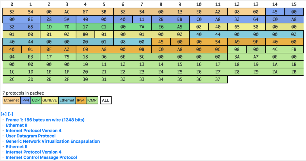
As both ports are located in different hypervisors, OVN is pushing the traffic via the overlay Geneve tunnel from Worker1 to Worker2. In the next post, we’ll analyze the Geneve encapsulation and how OVN uses its metadata internally.

For now, let’s ping from VM1 to VM2 and just capture traffic on the geneve interface on Worker2 to verify that ICMP packets are coming through the tunnel:

[root@worker2 ~]# tcpdump -i genev_sys_6081 -vvnn icmp
tcpdump: listening on genev_sys_6081, link-type EN10MB (Ethernet), capture size 262144 bytes
15:07:42.395318 IP (tos 0x0, ttl 64, id 45147, offset 0, flags [DF], proto ICMP (1), length 84)
    192.168.0.11 > 192.168.0.12: ICMP echo request, id 1251, seq 26, length 64
15:07:42.395383 IP (tos 0x0, ttl 64, id 39282, offset 0, flags [none], proto ICMP (1), length 84)
    192.168.0.12 > 192.168.0.11: ICMP echo reply, id 1251, seq 26, length 64
15:07:43.395221 IP (tos 0x0, ttl 64, id 45612, offset 0, flags [DF], proto ICMP (1), length 84)
    192.168.0.11 > 192.168.0.12: ICMP echo request, id 1251, seq 27, length 64

In coming posts we’ll cover Geneve encapsulation as well as OVN pipelines and L3 connectivity.

Simple OVN setup in 5 minutes

Open Virtual Network (OVN) is an awesome open source project which adds virtual network abstractions to Open vSwitch such as L2 and L3 overlays as well as managing connectivity to physical networks.

OVN has been integrated with OpenStack through networking-ovn which implements a Neutron ML2 driver to realize network resources such as networks, subnets, ports or routers. However, if you don’t want to go through the process of deploying OpenStack, this post provides a quick tutorial to get you started with OVN. (If you feel like it, you can use Packstack to deploy OpenStack RDO which by default will use OVN as the networking backend).

#!/bin/bash

# Disable SELinux
sudo setenforce 0
sudo sed -i 's/^SELINUX=.*/SELINUX=permissive/g' /etc/selinux/config

# Install pre-requisites to compile Open vSwitch
sudo yum group install "Development Tools" -y
sudo yum install python-devel python-six -y

GIT_REPO=${GIT_REPO:-https://github.com/openvswitch/ovs}
GIT_BRANCH=${GIT_BRANCH:-master}

# Clone ovs repo
git clone $GIT_REPO
cd ovs

if [[ "z$GIT_BRANCH" != "z" ]]; then
 git checkout $GIT_BRANCH
fi

# Compile the sources and install OVS
./boot.sh
CFLAGS="-O0 -g" ./configure --prefix=/usr
make -j5 V=0 install
sudo make install

# Start both OVS and OVN services
sudo /usr/share/openvswitch/scripts/ovs-ctl start --system-id="ovn"
sudo /usr/share/openvswitch/scripts/ovn-ctl start_ovsdb --db-nb-create-insecure-remote=yes --db-sb-create-insecure-remote=yes
sudo /usr/share/openvswitch/scripts/ovn-ctl start_northd
sudo /usr/share/openvswitch/scripts/ovn-ctl start_controller

# Configure OVN in OVSDB
sudo ovs-vsctl set open . external-ids:ovn-bridge=br-int
sudo ovs-vsctl set open . external-ids:ovn-remote=unix:/usr/var/run/openvswitch/ovnsb_db.sock
sudo ovs-vsctl set open . external-ids:ovn-encap-ip=127.0.0.1
sudo ovs-vsctl set open . external-ids:ovn-encap-type=geneve

After this, we have a functional OVN system which we can interact with by using the ovn-nbctl tool.

As an example, let’s create a very simple topology consisting on one Logical Switch and attach two Logical Ports to it:

# ovn-nbctl ls-add network1
# ovn-nbctl lsp-add network1 vm1
# ovn-nbctl lsp-add network1 vm2
# ovn-nbctl lsp-set-addresses vm1 "40:44:00:00:00:01 192.168.50.21"
# ovn-nbctl lsp-set-addresses vm2 "40:44:00:00:00:02 192.168.50.22"
# ovn-nbctl show
switch 6f2921aa-e679-462a-ae2b-b581cd958b82 (network1)
port vm2
addresses: ["40:44:00:00:00:02 192.168.50.22"]
port vm1
addresses: ["40:44:00:00:00:01 192.168.50.21"]

What now? Can we communicate vm1 and vm2 somehow?
At this point, we just defined our topology from a logical point of view but those ports are not bound to any hypervisor (Chassis in OVN terminology).

# ovn-sbctl show
Chassis ovn
 hostname: ovnhost
 Encap geneve
 ip: "127.0.0.1"
 options: {csum="true"}

# ovn-nbctl lsp-get-up vm1
down
# ovn-nbctl lsp-get-up vm2
down

For simplicity, let’s bind both ports “vm1” and “vm2” to our chassis simulating that we’re booting two virtual machines. If we would use libvirt or virtualbox to spawn the VMs, their integration with OVS would add the VIF ID to the external_ids:iface-id on the OVN bridge. Check this out for more information.


[root@ovnhost vagrant]# ovs-vsctl add-port br-int vm1 -- set Interface vm1 type=internal -- set Interface vm1 external_ids:iface-id=vm1
[root@ovnhost vagrant]# ovs-vsctl add-port br-int vm2 -- set Interface vm2 type=internal -- set Interface vm2 external_ids:iface-id=vm2
[root@ovnhost vagrant]# ovn-sbctl show
Chassis ovn
hostname: ovnhost
Encap geneve
ip: "127.0.0.1"
options: {csum="true"}
Port_Binding "vm2"
Port_Binding "vm1"
[root@ovnhost vagrant]# ovn-nbctl lsp-get-up vm1
up
[root@ovnhost vagrant]# ovn-nbctl lsp-get-up vm2
up

At this point we have both vm1 and vm2 bound to our chassis. This means that OVN installed the necessary flows in the OVS bridge for them. In order to test this communication, let’s create a namespace for each port and configure a network interface with the assigned IP and MAC addresses:


ip netns add vm1
ip link set vm1 netns vm1
ip netns exec vm1 ip link set vm1 address 40:44:00:00:00:01
ip netns exec vm1 ip addr add 192.168.50.21/24 dev vm1
ip netns exec vm1 ip link set vm1 up

ip netns add vm2
ip link set vm2 netns vm2
ip netns exec vm2 ip link set vm2 address 40:44:00:00:00:02
ip netns exec vm2 ip addr add 192.168.50.22/24 dev vm2
ip netns exec vm2 ip link set vm2 up

After this, we should be able to communicate vm1 and vm2 via the OVN Logical Switch:


[root@ovnhost vagrant]# ip netns list
vm2 (id: 1)
vm1 (id: 0)

[root@ovnhost vagrant]# ip netns exec vm1 ip addr
1: lo: <LOOPBACK> mtu 65536 qdisc noop state DOWN group default qlen 1000
link/loopback 00:00:00:00:00:00 brd 00:00:00:00:00:00
16: vm1: <BROADCAST,MULTICAST,UP,LOWER_UP> mtu 1500 qdisc noqueue state UNKNOWN group default qlen 1000
link/ether 40:44:00:00:00:01 brd ff:ff:ff:ff:ff:ff
inet 192.168.50.21/24 scope global vm1
valid_lft forever preferred_lft forever
inet6 fe80::4244:ff:fe00:1/64 scope link
valid_lft forever preferred_lft forever

[root@ovnhost vagrant]# ip netns exec vm2 ip addr
1: lo: <LOOPBACK> mtu 65536 qdisc noop state DOWN group default qlen 1000
link/loopback 00:00:00:00:00:00 brd 00:00:00:00:00:00
17: vm2: <BROADCAST,MULTICAST,UP,LOWER_UP> mtu 1500 qdisc noqueue state UNKNOWN group default qlen 1000
link/ether 40:44:00:00:00:02 brd ff:ff:ff:ff:ff:ff
inet 192.168.50.22/24 scope global vm2
valid_lft forever preferred_lft forever
inet6 fe80::4244:ff:fe00:2/64 scope link
valid_lft forever preferred_lft forever

[root@ovnhost vagrant]# ip netns exec vm1 ping -c2 192.168.50.22
PING 192.168.50.22 (192.168.50.22) 56(84) bytes of data.
64 bytes from 192.168.50.22: icmp_seq=1 ttl=64 time=0.326 ms
64 bytes from 192.168.50.22: icmp_seq=2 ttl=64 time=0.022 ms

--- 192.168.50.22 ping statistics ---
2 packets transmitted, 2 received, 0% packet loss, time 1000ms
rtt min/avg/max/mdev = 0.022/0.174/0.326/0.152 ms

[root@ovnhost vagrant]# ip netns exec vm2 ping -c2 192.168.50.21
PING 192.168.50.21 (192.168.50.21) 56(84) bytes of data.
64 bytes from 192.168.50.21: icmp_seq=1 ttl=64 time=0.025 ms
64 bytes from 192.168.50.21: icmp_seq=2 ttl=64 time=0.021 ms

--- 192.168.50.21 ping statistics ---
2 packets transmitted, 2 received, 0% packet loss, time 1000ms
rtt min/avg/max/mdev = 0.021/0.023/0.025/0.002 ms

In essence, what this post is describing is the OVN sandbox that comes out of the box with the OVS source code and presented by Russell Bryant . However, the idea behind this tutorial is to serve as a base to setup a simple OVN system as a playground or debugging environment without the burden of deploying OpenStack or any other CMS. In coming articles, we’ll extend the deployment to have more than one node and do more advanced stuff.

Implementing Security Groups in OpenStack using OVN Port Groups

Some time back, when looking at the performance of OpenStack using OVN as the networking backend, we noticed that it didn’t scale really well and it turned out that the major culprit was the way we implemented Neutron Security Groups . In order to illustrate the issue and the optimizations that we carried out, let’s first explain how security was originally implemented:

Networking-ovn and Neutron Security Groups

Originally, Security Groups were implemented using a combination of OVN resources such as Address Sets and Access Control Lists (ACLs):

  • Address Sets: An OVN Address set contains a number of IP addresses that can be referenced from an ACL. In networking-ovn  we directly map Security Groups to OVN Address Sets: every time a new IP address is allocated for a port, this address will be added to the Address Set(s) representing the Security Groups which the port belongs to.
$ ovn-nbctl list address_set
_uuid : 039032e4-9d98-4368-8894-08e804e9ee78
addresses : ["10.0.0.118", "10.0.0.123", "10.0.0.138", "10.0.0.143"]
external_ids : {"neutron:security_group_id"="0509db24-4755-4321-bb6f-9a094962ec91"}
name : "as_ip4_0509db24_4755_4321_bb6f_9a094962ec91"
  • ACLs: They are applied to a Logical Switch (Neutron network). They have a 1-to-many relationship with Neutron Security Group Rules. For instance, when the user creates a single Neutron rule within a Security Group to allow ingress ICMP traffic, it will map to N ACLs in OVN Northbound database with N being the number of ports that belong to that Security Group.
$ openstack security group rule create --protocol icmp default
_uuid : 6f7635ff-99ae-498d-8700-eb634a16903b
action : allow-related
direction : to-lport
external_ids : {"neutron:lport"="95fb15a4-c638-42f2-9035-bee989d80603", "neutron:security_group_rule_id"="70bcb4ca-69d6-499f-bfcf-8f353742d3ff"}
log : false
match : "outport == \"95fb15a4-c638-42f2-9035-bee989d80603\" && ip4 && ip4.src == 0.0.0.0/0 && icmp4"
meter : []
name : []
priority : 1002
severity : []

On the other hand, Neutron has the possibility to filter traffic between ports within the same Security Group or a remote Security Group. One use case may be: a set of VMs whose ports belong to SG1 only allowing HTTP traffic from the outside and another set of VMs whose ports belong to SG2 blocking all incoming traffic. From Neutron, you can create a rule to allow database connections from SG1 to SG2. In this case, in OVN we’ll see ACLs referencing the aforementioned Address Sets. In

$ openstack security group rule create --protocol tcp --dst-port 3306 --remote-group webservers default
+-------------------+--------------------------------------+
| Field | Value |
+-------------------+--------------------------------------+
| created_at | 2018-12-21T11:29:32Z |
| description | |
| direction | ingress |
| ether_type | IPv4 |
| id | 663012c1-67de-45e1-a398-d15bd4f295bb |
| location | None |
| name | None |
| port_range_max | 3306 |
| port_range_min | 3306 |
| project_id | 471603b575184afc85c67d0c9e460e85 |
| protocol | tcp |
| remote_group_id | 11059b7d-725c-4740-8db8-5c5b89865d0f |
| remote_ip_prefix | None |
| revision_number | 0 |
| security_group_id | 0509db24-4755-4321-bb6f-9a094962ec91 |
| updated_at | 2018-12-21T11:29:32Z |
+-------------------+--------------------------------------+

This gets the following OVN ACL into Northbound database:


_uuid : 03dcbc0f-38b2-42da-8f20-25996044e516
action : allow-related
direction : to-lport
external_ids : {"neutron:lport"="7d6247b7-65b9-4864-a9a0-a85bacb4d9ac", "neutron:security_group_rule_id"="663012c1-67de-45e1-a398-d15bd4f295bb"}
log : false
match : "outport == \"7d6247b7-65b9-4864-a9a0-a85bacb4d9ac\" && ip4 && ip4.src == $as_ip4_11059b7d_725c_4740_8db8_5c5b89865d0f && tcp && tcp.dst == 3306"
meter : []
name : []
priority : 1002
severity : []

Problem “at scale”

In order to best illustrate the impact of the optimizations that the Port Groups feature brought in OpenStack, let’s take a look at the number of ACLs on a typical setup when creating just 100 ports on a single network. All those ports will belong to a Security Group with the following rules:

  1. Allow incoming SSH traffic
  2. Allow incoming HTTP traffic
  3. Allow incoming ICMP traffic
  4. Allow all IPv4 traffic between ports of this same Security Group
  5. Allow all IPv6 traffic between ports of this same Security Group
  6. Allow all outgoing IPv4 traffic
  7. Allow all outgoing IPv6 traffic

Every time we create a port, new 10 ACLs (the 7 rules above + DHCP traffic ACL + default egress drop ACL + default ingress drop ACL) will be created in OVN:


$ ovn-nbctl list ACL| grep ce2ad98f-58cf-4b47-bd7c-38019f844b7b | grep match
match : "outport == \"ce2ad98f-58cf-4b47-bd7c-38019f844b7b\" && ip6 && ip6.src == $as_ip6_0509db24_4755_4321_bb6f_9a094962ec91"
match : "outport == \"ce2ad98f-58cf-4b47-bd7c-38019f844b7b\" && ip"
match : "outport == \"ce2ad98f-58cf-4b47-bd7c-38019f844b7b\" && ip4 && ip4.src == 0.0.0.0/0 && icmp4"
match : "inport == \"ce2ad98f-58cf-4b47-bd7c-38019f844b7b\" && ip4"
match : "outport == \"ce2ad98f-58cf-4b47-bd7c-38019f844b7b\" && ip4 && ip4.src == $as_ip4_0509db24_4755_4321_bb6f_9a094962ec91"
match : "inport == \"ce2ad98f-58cf-4b47-bd7c-38019f844b7b\" && ip6"
match : "outport == \"ce2ad98f-58cf-4b47-bd7c-38019f844b7b\" && ip4 && ip4.src == 0.0.0.0/0 && tcp && tcp.dst == 80"
match : "outport == \"ce2ad98f-58cf-4b47-bd7c-38019f844b7b\" && ip4 && ip4.src == 0.0.0.0/0 && tcp && tcp.dst == 22"
match : "inport == \"ce2ad98f-58cf-4b47-bd7c-38019f844b7b\" && ip4 && ip4.dst == {255.255.255.255, 10.0.0.0/8} && udp && udp.src == 68 && udp.dst == 67"
match : "inport == \"ce2ad98f-58cf-4b47-bd7c-38019f844b7b\" && ip"

With 100 ports, we’ll observe 1K ACLs in the system:

$ ovn-nbctl lsp-list neutron-ebde771e-a93d-438d-a689-d02e9c91c7cf | wc -l
100
$ ovn-nbctl acl-list neutron-ebde771e-a93d-438d-a689-d02e9c91c7cf | wc -l
1000

When ovn-northd sees these new ACLs, it’ll create the corresponding Logical Flows in Southbound database that will then be translated by ovn-controller to OpenFlow flows in the actual hypervisors. The number of Logical Flows also for this 100 ports system can be pulled like this:

$ ovn-sbctl lflow-list neutron-ebde771e-a93d-438d-a689-d02e9c91c7cf | wc -l
3052

At this point, you can pretty much tell that this doesn’t look very promising at scale.

Optimization

One can quickly spot an optimization consisting on having just one ACL per Security Group Rule instead of one ACL per Security Group Rule per port if only we could reference a set of ports and not each port individually on the ‘match’ column of an ACL. This would alleviate calculations mainly on the networking-ovn side where we saw a bottleneck at scale when processing new ports due to the high number of ACLs.

Such optimization would require a few changes on the core OVN side:

  • Changes to the schema to create a new table in the Northbound database (Port_Group) and to be able to apply ACLs also to a Port Group.
  • Changes to ovn-northd so that it creates new Logical Flows based on ACLs applied to Port Groups.
  • Changes to ovn-controller so that it can figure out the physical flows to install on every hypervisor based on the new Logical Flows.

These changes happened mainly in the next 3 patches and the feature is present in OvS 2.10 and beyond:

https://github.com/openvswitch/ovs/commit/3d2848bafa93a2b483a4504c5de801454671dccf

https://github.com/openvswitch/ovs/commit/1beb60afd25a64f1779903b22b37ed3d9956d47c

https://github.com/openvswitch/ovs/commit/689829d53612a573f810271a01561f7b0948c8c8

On the networking-ovn side, we needed to adapt the code as well to:

  • Make use of the new feature and implement Security Groups using Port Groups.
  • Ensure a migration path from old implementation to Port Groups.
  • Keep backwards compatibility: in case an older version of OvS is used, we need to fall back to the previous implementation.

Here you can see the main patch to accomplish the changes above:

https://github.com/openstack/networking-ovn/commit/f01169b405bb5080a1bc1653f79512eb0664c35d

If we attempt to recreate the same scenario as we did earlier where we had 1000 ACLs for 100 ports on our Security Group using the new feature, we can compare the number of resources that we’re now using:

$ ovn-nbctl lsp-list neutron-ebde771e-a93d-438d-a689-d02e9c91c7cf | wc -l
100

Two OVN Port Groups have been created: one for our Security Group and then neutron-pg-drop which is used to add fallback, low priority drop ACLs (by default OVN will allow all traffic if no explicit drop ACLs are added):

$ ovn-nbctl --bare --columns=name list Port_Group
neutron_pg_drop
pg_0509db24_4755_4321_bb6f_9a094962ec91

ACLs are now applied to Port Groups and not to the Logical Switch:

$ ovn-nbctl acl-list neutron-ebde771e-a93d-438d-a689-d02e9c91c7cf | wc -l
0
$ ovn-nbctl acl-list pg_0509db24_4755_4321_bb6f_9a094962ec91 | wc -l
7
$ ovn-nbctl acl-list neutron_pg_drop | wc -l
2

The number of ACLs has gone from 1000 (10 per port) to just 9 regardless of the number of ports in the system:

$ ovn-nbctl --bare --columns=match list ACL
inport == @pg_0509db24_4755_4321_bb6f_9a094962ec91 && ip4
inport == @pg_0509db24_4755_4321_bb6f_9a094962ec91 && ip6
inport == @neutron_pg_drop && ip
outport == @pg_0509db24_4755_4321_bb6f_9a094962ec91 && ip4 && ip4.src == 0.0.0.0/0 && tcp && tcp.dst == 22
outport == @pg_0509db24_4755_4321_bb6f_9a094962ec91 && ip4 && ip4.src == 0.0.0.0/0 && icmp4
outport == @pg_0509db24_4755_4321_bb6f_9a094962ec91 && ip6 && ip6.src == $pg_0509db24_4755_4321_bb6f_9a094962ec91_ip6
outport == @pg_0509db24_4755_4321_bb6f_9a094962ec91 && ip4 && ip4.src == $pg_0509db24_4755_4321_bb6f_9a094962ec91_ip4
outport == @pg_0509db24_4755_4321_bb6f_9a094962ec91 && ip4 && ip4.src == 0.0.0.0/0 && tcp && tcp.dst == 80
outport == @neutron_pg_drop && ip


This change was merged in OpenStack Queens and requires OvS 2.10 at least. Also, if upgrading from an earlier version of either OpenStack or OvS, networking-ovn will take care of the migration from Address Sets to Port Groups upon start of Neutron server and the new implementation will be automatically used.

As  a bonus, this enables the possibility of applying the conjunctive match action easier on Logical Flows resulting in a big performance improvement as it was reported here.

Some fun with race conditions and threads in OpenStack

Almost a year ago I reported a bug we were hitting in OpenStack using networking-ovn as a network backend. The symptom was that sometimes Tempest tests were failing in the gate when trying to reach a Floating IP of a VM. The failure rate was not really high so a couple of ‘rechecks’ here and there was enough for us to delay chasing down the bug.

Last week I decided to hunt the bug and attempt to find out the root cause of the failure. Why was the FIP unreachable? For a FIP to be reachable from the external network (Tempest), the following high-level steps should happen:

  1. Tempest needs to ARP query the FIP of the VM
  2. A TCP SYN packet is sent out to the FIP
  3. Routing will happen between external network and internal VM network
  4. The packet will reach the VM and it’ll respond back with a SYN/ACK packet to the originating IP (Tempest executor)
  5. Routing will happen between internal VM network and external network
  6. SYN/ACK packet reaches Tempest executor and the connection will get established on its side
  7. ACK sent to the VM

Some of those steps are clearly failing so time to figure out which.

2018-09-18 17:09:17,276 13788 ERROR [tempest.lib.common.ssh] Failed to establish authenticated ssh connection to cirros@172.24.5.11 after 15 attempts

As first things come first, let’s start off by checking that we get the ARP response of the FIP. We spawn a tcpdump on the external interface where Tempest runs and check traffic to/from 172.24.5.11:

Sep 18 17:09:17.644405 ubuntu-xenial-ovh-bhs1-0002095917 tcpdump[28445]: 17:09:17.275597 1e:d5:ec:49:df:4f > ff:ff:ff:ff:ff:ff, ethertype ARP (0x0806), length 42: Request who-has 172.24.5.11 tell 172.24.5.1, length 28

I can see plenty of those ARP requests but not a single reply. Something’s fishy…

In OVN, ARP queries are responded by ovn-controller so they should hit the gateway node. Let’s inspect the flows there to see if they were installed in OVN Ingress table 1 (which corresponds to OpenFlow table 9):

http://www.openvswitch.org/support/dist-docs/ovn-northd.8.html

Ingress Table 1: IP Input

These flows reply to ARP requests for the virtual IP
addresses configured in the router for DNAT or load bal‐
ancing. For a configured DNAT IP address or a load bal‐
ancer VIP A, for each router port P with Ethernet address
E, a priority-90 flow matches inport == P && arp.op == 1
&& arp.tpa == A (ARP request) with the following actions:

eth.dst = eth.src;
eth.src = E;
arp.op = 2; /* ARP reply. */
arp.tha = arp.sha;
arp.sha = E;
arp.tpa = arp.spa;
arp.spa = A;
outport = P;
flags.loopback = 1;
output;


$ sudo ovs-ofctl dump-flows br-int | grep table=9 | grep "arp_tpa=172.24.5.11"
cookie=0x549ad196, duration=105.055s, table=9, n_packets=0, n_bytes=0, idle_age=105, priority=90,arp,reg14=0x1,metadata=0x87,arp_tpa=172.24.5.11,arp_op=1 actions=move:NXM_OF_ETH_SRC[]->NXM_OF_ETH_DST[],load:0x2->NXM_OF_ARP_OP[],move:NXM_NX_ARP_SHA[]->NXM_NX_ARP_THA[],mod_dl_src:fa:16:3e:3d:bf:46,load:0xfa163e3dbf46->NXM_NX_ARP_SHA[],move:NXM_OF_ARP_SPA[]->NXM_OF_ARP_TPA[],load:0xac18050b->NXM_OF_ARP_SPA[],load:0x1->NXM_NX_REG15[],load:0x1->NXM_NX_REG10[0],resubmit(,32)

So the flow for the ARP responder is installed but it has no hits (note n_packets=0). Looks like for some reason the ARP query is not reaching the router pipeline from the public network. Let’s now take a look at the Logical Router:

This is how the Logical Router looks like:

$ ovn-nbctl show
router 71c37cbd-4aa9-445d-a9d1-cb54ee1d3207 (neutron-cc163b42-1fdf-4cfa-a2ff-50c521f04222) (aka tempest-TestSecurityGroupsBasicOps-router-1912572360)
     port lrp-2a1bbf89-adee-4e74-b65e-1ac7a1ba4089
         mac: "fa:16:3e:3d:bf:46"
         networks: ["10.1.0.1/28"]
     nat 2eaaa99e-3be8-49ad-b801-ad198a6084fd
         external ip: "172.24.5.7"
         logical ip: "10.1.0.0/28"
         type: "snat"
     nat 582bab87-8acb-4905-8723-948651811193
         external ip: "172.24.5.11"
         logical ip: "10.1.0.6"
         type: "dnat_and_snat"

We can see that we have two NAT entries: one for the FIP (172.24.5.11 <-> 10.1.0.6) and one SNAT entry for the gateway which should allow the VM to access the external network.

There’s also one router port which connects the VM subnet to the router but… wait …There’s no gateway port connected to the router!! This means that the FIP is unreachable so at this point we know what’s going on but… WHY? We need to figure out why the gateway port is not added. Time to check the code and logs:

Code wise (see below), the gateway is added upon router creation. It’ll imply creating a router (L9), the gateway port (L26) and adding it to the Logical Switch as you can see here. Afterwards, it’ll add a static route with the next hop to the router (L37). Also, you can see that everything is inside a context manager (L8) where a transaction with OVSDB is created so all the commands are expected to be commited/failed as a whole:

def create_router(self, router, add_external_gateway=True):
    """Create a logical router."""
    context = n_context.get_admin_context()
    external_ids = self._gen_router_ext_ids(router)
    enabled = router.get('admin_state_up')
    lrouter_name = utils.ovn_name(router['id'])
    added_gw_port = None
    with self._nb_idl.transaction(check_error=True) as txn:
        txn.add(self._nb_idl.create_lrouter(lrouter_name,
                                            external_ids=external_ids,
                                            enabled=enabled,
                                            options={}))
        if add_external_gateway:
            networks = self._get_v4_network_of_all_router_ports(
                context, router['id'])
            if router.get(l3.EXTERNAL_GW_INFO) and networks is not None:
                added_gw_port = self._add_router_ext_gw(context, router,
                                                        networks, txn)

def _add_router_ext_gw(self, context, router, networks, txn):
    router_id = router['id']
    # 1. Add the external gateway router port.
    gw_info = self._get_gw_info(context, router)
    gw_port_id = router['gw_port_id']
    port = self._plugin.get_port(context, gw_port_id)
    self._create_lrouter_port(router_id, port, txn=txn)

    columns = {}
    if self._nb_idl.is_col_present('Logical_Router_Static_Route',
                                   'external_ids'):
        columns['external_ids'] = {
            ovn_const.OVN_ROUTER_IS_EXT_GW: 'true',
            ovn_const.OVN_SUBNET_EXT_ID_KEY: gw_info.subnet_id}

    # 2. Add default route with nexthop as gateway ip
    lrouter_name = utils.ovn_name(router_id)
    txn.add(self._nb_idl.add_static_route(
        lrouter_name, ip_prefix='0.0.0.0/0', nexthop=gw_info.gateway_ip,
        **columns))

    # 3. Add snat rules for tenant networks in lrouter if snat is enabled
    if utils.is_snat_enabled(router) and networks:
        self.update_nat_rules(router, networks, enable_snat=True, txn=txn)
    return port

So, how is it possible that the Logical Router exists while the gateway port does not if everything is under the same transaction? We’re nailing this down and now we need to figure that out by inspecting the transactions in neutron-server logs:

DEBUG ovsdbapp.backend.ovs_idl.transaction [-] Running txn n=1 command(idx=2): AddLRouterCommand(may_exist=True, columns={'external_ids': {'neutron:gw_port_id': u'8dc49792-b37a-48be-926a-af2c76e269a9', 'neutron:router_name': u'tempest-TestSecurityGroupsBasicOps-router-1912572360', 'neutron:revision_number': '2'}, 'enabled': True, 'options': {}}, name=neutron-cc163b42-1fdf-4cfa-a2ff-50c521f04222) {{(pid=32314) do_commit /usr/local/lib/python2.7/dist-packages/ovsdbapp/backend/ovs_idl/transaction.py:84}}

The above trace is written when the Logical Router gets created but surprisingly we can see idx=2 meaning that it’s not the first command of a transaction. But… How is this possible? We saw in the code that it was the first command to be executed when creating a router and this is the expected sequence:

  1. AddLRouterCommand
  2. AddLRouterPortCommand
  3. SetLRouterPortInLSwitchPortCommand
  4. AddStaticRouteCommand

Let’s check the other commands in this transaction in the log file:

DEBUG ovsdbapp.backend.ovs_idl.transaction [-] Running txn n=1 command(idx=0): AddLRouterPortCommand(name=lrp-1763c78f-5d0d-41d4-acc7-dda1882b79bd, may_exist=True, lrouter=neutron-d1d3b2f2-42cb-4a86-ac5a-77001da8fee2, columns={'mac': u'fa:16:3e:e7:63:b9', 'external_ids': {'neutron:subnet_ids': u'97d41327-4ea6-4fff-859c-9884f6d1632d', 'neutron:revision_number': '3', 'neutron:router_name': u'd1d3b2f2-42cb-4a86-ac5a-77001da8fee2'}, 'networks': [u'10.1.0.1/28']}) {{(pid=32314) do_commit /usr/local/lib/python2.7/dist-packages/ovsdbapp/backend/ovs_idl/transaction.py:84}}

DEBUG ovsdbapp.backend.ovs_idl.transaction [-] Running txn n=1 command(idx=1): SetLRouterPortInLSwitchPortCommand(if_exists=True, lswitch_port=1763c78f-5d0d-41d4-acc7-dda1882b79bd, lrouter_port=lrp-1763c78f-5d0d-41d4-acc7-dda1882b79bd, is_gw_port=False, lsp_address=router) {{(pid=32314) do_commit /usr/local/lib/python2.7/dist-packages/ovsdbapp/backend/ovs_idl/transaction.py:84}}

DEBUG ovsdbapp.backend.ovs_idl.transaction [-] Running txn n=1 command(idx=2): AddLRouterCommand(may_exist=True, columns={'external_ids': {'neutron:gw_port_id': u'8dc49792-b37a-48be-926a-af2c76e269a9', 'neutron:router_name': u'tempest-TestSecurityGroupsBasicOps-router-1912572360', 'neutron:revision_number': '2'}, 'enabled': True, 'options': {}}, name=neutron-cc163b42-1fdf-4cfa-a2ff-50c521f04222)

DEBUG ovsdbapp.backend.ovs_idl.transaction [-] Running txn n=1 command(idx=3): AddNATRuleInLRouterCommand(lrouter=neutron-d1d3b2f2-42cb-4a86-ac5a-77001da8fee2, columns={'external_ip': u'172.24.5.26', 'type': 'snat', 'logical_ip': '10.1.0.0/28'}) {{(pid=32314) do_commit /usr/local/lib/python2.7/dist-packages/ovsdbapp/backend/ovs_idl/transaction.py:84}}

It looks like this:

  1. AddLRouterPortCommand
  2. SetLRouterPortInLSwitchPortCommand
  3. AddLRouterCommand (our faulty router)
  4. AddNATRuleInLRouterCommand

Definitely, number 3 is our command that got in between a totally different transaction from a totally different test being executed concurrently in the gate . Most likely, according to the commands 1, 2 and 4 it’s another test adding a new interface to a different router here. It’ll create a logical router port, add it to the switch and update the SNAT rules. All those debug traces come from the same process ID so the transactions are getting messed up from the two concurrent threads attempting to write into OVSDB.

This is the code that will create a new transaction object in ovsdbapp or, if it was already created, will return the same object. The problem here comes when two different threads/greenthreads attempt to create their own separate transactions concurrently:

    @contextlib.contextmanager
    def transaction(self, check_error=False, log_errors=True, **kwargs):
        """Create a transaction context.

        :param check_error: Allow the transaction to raise an exception?
        :type check_error:  bool
        :param log_errors:  Log an error if the transaction fails?
        :type log_errors:   bool
        :returns: Either a new transaction or an existing one.
        :rtype: :class:`Transaction`
        """
        if self._nested_txn:
            yield self._nested_txn
        else:
            with self.create_transaction(
                    check_error, log_errors, **kwargs) as txn:
                self._nested_txn = txn
                try:
                    yield txn
                finally:
                    self._nested_txn = None
  1. Test1 will open a new transaction and append  AddLRouterPortCommand and SetLRouterPortInLSwitchPortCommand commands to it.
  2. Test1 will now yield its execution (due to some I/O in the case of greenthreads as eventlet is heavily used in OpenStack).
  3. Test 2 (our failing test!) will attempt to create its own transaction.
  4. As everything happens in the same process, self._nested_txn was previously assigned due to step number 1 and is returned here.
  5. Test 2 will append the  AddLRouterCommand command to it.
  6. At this point Test 2 will also yield its execution. Mainly due to the many debug traces that we have for scheduling a gateway port on the available chassis in OVN so this is one of the most likely parts of the code for the race condition to occur.
  7. Test 1 will append the rest of the commands and commit the transaction to OVSDB.
  8. OVSDB will execute the commands and close the transaction.
  9. When Test 2 appends the rest of its commands, the transaction is closed and will never get commited, ie. only AddLRouterCommand was applied to the DB leaving the gateway port behind in OVN.

The nested transaction mechanism in ovsdbapp was not taking into account that two different threads attempt to open separate transactions so we needed to patch this to make it thread safe. The solution that we came up with was to create a different transaction per thread ID and add the necessary coverage to the unit tests.

Two more questions arise at this point:

  • Why this is not happening in Neutron if they also use ovsdbapp there?

Perhaps it’s happening but they don’t make that much use of multiple commands transactions. Instead, most of the time it’s single command transactions that are less prone to this particular race condition.

  • Why does it happen mostly when creating a gateway port?

Failing to create a gateway port leads to VMs to lose external connectivity so the failure is very obvious. There might be other conditions where this bug happens and we’re not even realizing, producing weird behaviors. However, it’s true that this particular code which creates the gateway port is complex as it implies scheduling the port into the least loaded available chassis so a number of DEBUG traces were added. As commented through the blog post, writing these traces will result in yielding the execution to a different greenthread where the disaster occurs!

This blog post tries to show a top-bottom approach to debugging failures that are not easily reproducible. It requires a solid understanding of the system architecture (OpenStack components, OVN, databases) and its underlying technologies (Python, greenthreads) to be able to tackle this kind of race conditions in an effective way.
OVN – Profiling and optimizing ports creation

One of the most important abstractions to handle virtual networking in OpenStack clouds are definitely ports. A port is basically a connection point for attaching a single device, such as the NIC of a server to a network, a subnet to a router, etc.  They represent entry and exit points for data traffic playing a critical role in OpenStack networking.

Given the importance of ports, it’s clear that any operation on them should perform well, specially at scale and we should be able to catch any regressions ASAP before they land on production environments. Such tests should be done in a periodic fashion and should require doing them on a consistent hardware with enough resources.

In one of our first performance tests using OVN as a backend for OpenStack networking, we found out that port creation would be around 20-30% slower than using ML2/OVS. At this point, those are merely DB operations so there had to be something really odd going on.  First thing I did was to measure the time for a single port creation by creating 800 ports in an empty cloud. Each port would belong to a security group with allowed egress traffic and allowed ingress ICMP and SSH. These are the initial results:

As you can see, the time for creating a single port grows linearly with the number of ports in the cloud.  This is obviously a problem at scale that requires further investigation.

In order to understand how a port gets created in OVN, it’s recommended to take a look at the NorthBound database schema and to this interesting blogpost by my colleague Russel Bryant about how Neutron security groups are implemented in OVN. When a port is first created in OVN, the following DB operations will occur:

  1.  Logical_Switch_Port ‘insert’
  2.  Address_Set ‘modify’
  3.  ACL ‘insert’ x8 (one per ACL)
  4.  Logical_Switch_Port ‘modify’ (to add the new 8 ACLs)
  5.  Logical_Switch_Port ‘modify’ (‘up’ = False)

After a closer look to OVN NB database contents, with 800 ports created, there’ll be a total of 6400 ACLs (8 per port) which look all the same except for the inport/outport fields. A first optimization looks obvious: let’s try to get all those 800 ports into the same group and make the ACLs reference that group avoiding duplication. There’s some details and discussions in OpenvSwitch mailing list here. So far so good; we’ll be cutting down the number of ACLs to 8 in this case no matter how big the number of ports in the system increases. This would reduce the number of DB operations considerably and scale better.

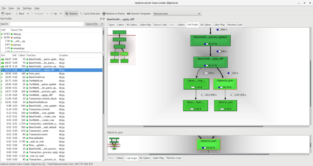
However, I went deeper and wanted to understand this linear growth through profiling. I’d like to write a separate blogpost about how to do the profiling but, so far, what I found is that the ‘modify’ operations on the Logical_Switch table to insert the new 8 ACLs would take longer and longer every time (the same goes to the Address_Set table where a new element is added to it with every new port). As the number of elements grow in those two tables, inserting a new element was more expensive. Digging further in the profiling results, it looks like “__apply_diff()” method is the main culprit, and more precisely, “Datum.to_json()”. Here‘s a link to the actual source code.

Whenever a ‘modify’ operation happens in OVSDB, ovsdb-server will send a JSON  update notification to all clients (it’s actually an update2 notification which is essentially the same but including only the diff with the previous state). This notification is going to be processed by the client (in this case networking-ovn, the OpenStack integration) in the “process_update2” method here and it happens that the Datum.to_json() method is taking most of the execution time. The main questions that came to my mind at this point are:

  1. How is this JSON data later being used?
  2. Why do we need to convert to JSON if the original notification was already in JSON?

For 1, it looks like the JSON data is used to build a Row object which will be then used to notify networking-ovn of the change just in case it’d be monitoring any events:

    def __apply_diff(self, table, row, row_diff):
        old_row_diff_json = {}
        for column_name, datum_diff_json in six.iteritems(row_diff):
            [...]
            old_row_diff_json[column_name] = row._data[column_name].to_json()
            [...]
        return old_row_diff_json
old_row_diff_json = self.__apply_diff(table, row,
                                      row_update['modify'])
self.notify(ROW_UPDATE, row,
            Row.from_json(self, table, uuid, old_row_diff_json))

Doesn’t it look pointless to convert data “to_json” and then back “from_json”? As the number of elements in the row grows, it’ll take longer to produce the associated JSON document (linear growth) of the whole column contents (not just the diff) and the same would go the other way around.

I thought of finding a way to build the Row from the data itself before going through the expensive (and useless) JSON conversions. The patch would look something like this:

diff --git a/python/ovs/db/idl.py b/python/ovs/db/idl.py
index 60548bcf5..5a4d129c0 100644
--- a/python/ovs/db/idl.py
+++ b/python/ovs/db/idl.py
@@ -518,10 +518,8 @@ class Idl(object):
             if not row:
                 raise error.Error('Modify non-existing row')
 
-            old_row_diff_json = self.__apply_diff(table, row,
-                                                  row_update['modify'])
-            self.notify(ROW_UPDATE, row,
-                        Row.from_json(self, table, uuid, old_row_diff_json))
+            old_row = self.__apply_diff(table, row, row_update['modify'])
+            self.notify(ROW_UPDATE, row, Row(self, table, uuid, old_row))
             changed = True
         else:
             raise error.Error('<row-update> unknown operation',
@@ -584,7 +582,7 @@ class Idl(object):
                         row_update[column.name] = self.__column_name(column)
 
     def __apply_diff(self, table, row, row_diff):
-        old_row_diff_json = {}
+        old_row = {}
         for column_name, datum_diff_json in six.iteritems(row_diff):
             column = table.columns.get(column_name)
             if not column:
@@ -601,12 +599,12 @@ class Idl(object):
                           % (column_name, table.name, e))
                 continue
 
-            old_row_diff_json[column_name] = row._data[column_name].to_json()
+            old_row[column_name] = row._data[column_name].copy()
             datum = row._data[column_name].diff(datum_diff)
             if datum != row._data[column_name]:
                 row._data[column_name] = datum
 
-        return old_row_diff_json
+        return old_row
 
     def __row_update(self, table, row, row_json):
         changed = False

Now that we have everything in place, it’s time to repeat the tests with the new code and compare the results:

The improvement is obvious! Now the time to create a port is mostly constant regardless of the number of ports in the cloud and the best part is that this gain is not specific to port creation but to ANY modify operation taking place in OVSDB that uses the Python implementation of the OpenvSwitch IDL.

The intent of this blogpost is to show how to deal with performance bottlenecks through profiling and debugging in a top-down fashion, first through simple API calls measuring the time they take to complete and then all the way down to the database changes notifications.

Daniel

OpenStack: Deploying a new containerized service in TripleO

When I first started to work in networking-ovn one of the first tasks I took up was to implement the ability for instances to fetch userdata and metadata at boot, such as the name of the instance, public keys, etc.

This involved introducing a new service which we called networking-ovn-metadata-agent and it’s basically a process running in compute nodes that intercepts requests from instances within network namespaces, adds some headers and forwards those to Nova. While it was fun working on it I soon realized that most of the work would be on the TripleO side and, since I was really new to it, I decided to take the challenge as well!
If you’re interested in the actual code for this feature (not the deployment related code), I sent the following patches to implement it and I plan to write a different blogpost for it:

But implementing this feature didn’t end there and we had to support a way to deploy the new service from TripleO and, YES!, it has to be containerized. I found out that this was not a simple task so I decided to write this post with the steps I took hoping it helps people going through the same process. Before describing those, I want to highlight a few things/tips:

  • It’s highly recommended to have access to a hardware capable of deploying TripleO and not relying only on the gate. This will speed up the development process *a lot* and lower pressure on the gate, which sometimes has really long queues.
  • The jobs running on the upstream CI use one node for the undercloud and one node for the overcloud so it’s not always easy to catch failures when you deploy services on certain roles like in this case where we only want the new service in computes.  CI was green on certain patchsets while I encountered problems on 3 controllers + 3 computes setups due to this. Usually production environments would be HA so it’s best to do the development on a more realistic setups whenever possible.
  • As of today, with containers, there’s no way that you can send a patch on your project (in this case networking-ovn), add a Depends-On in tripleo-* and expect that the new change is tested. Instead, the patch has to get merged, an RDO promotion has to occur so that the RPM with the fix is available and then, the container images get built and ready to be fetched by TripleO jobs. This is a regression when compared to non-containerized jobs and clearly slows down the development process. TripleO folks are doing a great effort to include a mechanism that supports this which will be a huge leap 🙂
  • To overcome the above, I had to go over the process of building my own kolla images and setting them up in the local registry (more info here). This way you can do your own testing without having to wait for the next RDO promotion. Still, your patches won’t be able to merge until it happens but you can keep on developing your stuff.
  • To test any puppet changes, I had to patch the overcloud image (usually mounting it with guestmount and changing the required files) and update it before redeploying. This is handy as well as the ‘virt-customize’ command  which allows you to execute commands directly in the overcloud image, for example, to install a new RPM package (for me usually upgrading OpenvSwitch for testing). This is no different from baremetal deployment but still useful here.

After this long introduction, let me go through the actual code that implements this new service.


1. Getting the package and the container image ready:

At this point we should be able to consume the container image from TripleO. The next step is to configure the new service with the right parameters.

2. New service configuration:

puppet-neutron:

This new service will require some configuration options. Writing those configuration options will be done by puppet and, since it is a networking service, I sent a patch to puppet-neutron to support it: https://review.openstack.org/#/c/502941/

All the configuration options as well as the service definition are in this file:

https://review.openstack.org/#/c/502941/9/manifests/agents/ovn_metadata.pp

As we also want to set a knob which enables/disables the service in the ML2 plugin, I added an option for that here:

https://review.openstack.org/#/c/502941/9/manifests/plugins/ml2/ovn.pp@59

The patch also includes unit tests and a release note as we’re introducing a new service.

puppet-tripleo:

We want this service to be deployed at step 4 (see OpenStack deployment steps for more information) and also, we want networking-ovn-metadata-agent to be started after ovn-controller is up and running. ovn-controller service will be started after OpenvSwitch so this way we’ll ensure that our service will start at the right moment. For this, I sent a patch to puppet-tripleo:

https://review.openstack.org/#/c/502940/

And later, I found out that I wanted the neutron base profile configuration to be applied to my own service. This way I could benefit from some Neutron common configuration such as logging files, etc.: https://review.openstack.org/527482

3. Actual deployment in tripleo-heat-templates:

This is the high-level work that drives all the above and, initially, I had it in three different patches which I ended up squashing because of the inter-dependencies.

https://review.openstack.org/#/c/502943/

To sum up, this is what this patch does

I hope this help others introducing new services in OpenStack! Feel free to reach out to me for any comments/corrections/suggestions by e-mail or on IRC 🙂

Encrypting your connections with stunnel

stunnel is an open source software that provides SSL/TLS tunneling. This is especially useful when it comes to protect existing client-server communications that do not provide any encryption at all. Another application is to avoid exposing many services and make all of them pass through the tunnel and, therefore, securing all the traffic at the same time.

And because I have a WR703N with an OpenVPN server installed, I decided to set up stunnel and give it a try. The advantage over using my existing VPN, under certain circumstances, is that the establishment of the secure tunnel looks pretty much like a normal connection to an HTTPS website so most of the networks/proxys will allow this traffic whilst the VPN might be blocked (especially if UDP is used). So, the OpenVPN+stunnel combo looks like a pretty good security solution to be installed on our OpenWRT device.

The way I have the stunnel service configured is using MTLS (client and server authentication) and allowing only TLSv1.2 protocol. These are the specific lines in the stunnel.conf (server side):

; protocol version (all, SSLv2, SSLv3, TLSv1)
sslVersion = all
options = CIPHER_SERVER_PREFERENCE
options = NO_SSLv2
options = NO_SSLv3
options = NO_TLSv1

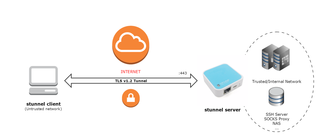
Just for testing, I have installed stunnel on a Windows box and configured it as a client (with a client certificate signed by the same CA as the server) and connections to server port 443 will be forwarded to the SSH service running on the server side. This would allow us to SSH our server without
needing to expose it and, for example, set up a SOCKS proxy and browse the internet securely through the tunnel.

stunnel Diagram

Client side:

[https]
accept  = 22
protocol = connect
connect = proxy:8080
protocolHost= server:443

Server side:

[https]
accept  = 443
connect = 22
TIMEOUTclose = 0

On the client side, simply SSH localhost on the configured port (22) and stunnel will intercept this connection and establish a TLS tunnel with the server to the SSH service running on it.

These are the logs on the client side when SSH’ing localhost:

2016.07.20 21:37:09 LOG7[12]: Service [https] started
2016.07.20 21:37:09 LOG5[12]: Service [https] accepted connection from 127.0.0.1:43858
2016.07.20 21:37:09 LOG6[12]: s_connect: connecting proxy:8080
2016.07.20 21:37:09 LOG7[12]: s_connect: s_poll_wait proxy:8080: waiting 10 seconds
2016.07.20 21:37:09 LOG5[12]: s_connect: connected proxy:8080
2016.07.20 21:37:09 LOG5[12]: Service [https] connected remote server from x.x.x.x:43859
2016.07.20 21:37:09 LOG7[12]: Remote descriptor (FD=732) initialized
2016.07.20 21:37:09 LOG7[12]:  -> CONNECT server:443 HTTP/1.1
2016.07.20 21:37:09 LOG7[12]:  -> Host: server:443
2016.07.20 21:37:09 LOG7[12]:  -> Proxy-Authorization: basic **
2016.07.20 21:37:09 LOG7[12]:  -> 
2016.07.20 21:37:09 LOG7[12]:  <- HTTP/1.1 200 Connection established
2016.07.20 21:37:09 LOG6[12]: CONNECT request accepted
2016.07.20 21:37:09 LOG7[12]:  <- 
2016.07.20 21:37:09 LOG6[12]: SNI: sending servername: server
2016.07.20 21:37:09 LOG7[12]: SSL state (connect): before/connect initialization
2016.07.20 21:37:09 LOG7[12]: SSL state (connect): SSLv3 write client hello A
2016.07.20 21:37:11 LOG7[12]: SSL state (connect): SSLv3 read server hello A
2016.07.20 21:37:11 LOG7[12]: Verification started at depth=1: C=ES, ST=M, O=O, CN=wrtServer
2016.07.20 21:37:11 LOG7[12]: CERT: Pre-verification succeeded
2016.07.20 21:37:11 LOG6[12]: Certificate accepted at depth=1: C=ES, ST=M, O=O, CN=wrtServer
2016.07.20 21:37:11 LOG7[12]: Verification started at depth=0: C=ES, ST=S, O=O, CN=wrtClient
2016.07.20 21:37:11 LOG7[12]: CERT: Pre-verification succeeded
2016.07.20 21:37:11 LOG5[12]: Certificate accepted at depth=0: C=ES, ST=S, O=O, CN=wrtClient
2016.07.20 21:37:11 LOG7[12]: SSL state (connect): SSLv3 read server certificate A
2016.07.20 21:37:11 LOG7[12]: SSL state (connect): SSLv3 read server key exchange A
2016.07.20 21:37:11 LOG6[12]: Client CA: C=ES, ST=M, O=O, CN=wrtCA
2016.07.20 21:37:11 LOG7[12]: SSL state (connect): SSLv3 read server certificate request A
2016.07.20 21:37:11 LOG7[12]: SSL state (connect): SSLv3 read server done A
2016.07.20 21:37:11 LOG7[12]: SSL state (connect): SSLv3 write client certificate A
2016.07.20 21:37:11 LOG7[12]: SSL state (connect): SSLv3 write client key exchange A
2016.07.20 21:37:11 LOG7[12]: SSL state (connect): SSLv3 write certificate verify A
2016.07.20 21:37:11 LOG7[12]: SSL state (connect): SSLv3 write change cipher spec A
2016.07.20 21:37:11 LOG7[12]: SSL state (connect): SSLv3 write finished A
2016.07.20 21:37:11 LOG7[12]: SSL state (connect): SSLv3 flush data
2016.07.20 21:37:11 LOG7[12]: SSL state (connect): SSLv3 read server session ticket A
2016.07.20 21:37:11 LOG7[12]: SSL state (connect): SSLv3 read finished A
2016.07.20 21:37:11 LOG7[12]:      8 client connect(s) requested
2016.07.20 21:37:11 LOG7[12]:      7 client connect(s) succeeded
2016.07.20 21:37:11 LOG7[12]:      0 client renegotiation(s) requested
2016.07.20 21:37:11 LOG7[12]:      2 session reuse(s)
2016.07.20 21:37:11 LOG6[12]: SSL connected: new session negotiated
2016.07.20 21:37:11 LOG7[12]: Deallocating application specific data for addr index
2016.07.20 21:37:11 LOG6[12]: Negotiated TLSv1.2 ciphersuite ECDHE-RSA-AES256-GCM-SHA384 (256-bit encryption)

As you can see, the traffic will be routed through a TLSv1.2 channel encrypted with AES256 in GCM mode and the session key has been derived using ephimeral ECDH, with Perfect Forward Secrecy so the traffic will be fairly well protected, at least, up to the stunnel server.

Make sure to keep an eye on the vulnerabilities listed on the stunnel website and have the server properly patched.

Building RPM packages

I wanted to learn how to build an RPM package out of a Python module so, now that I’m playing a bit with OpenStack, I decided to pick up a log merger for OpenStack files and build the corresponding package on my Fedora 24.

First thing is to setup the distribution with the right packages:

[root@localhost ~]$ dnf install @development-tools fedora-packager
[dani@localhost ~]$ rpmdev-setuptree
[dani@localhost ~]$ ls rpmbuild/
BUILD  BUILDROOT  RPMS  SOURCES  SPECS  SRPMS

Now, under the SPECS directory, we need to create the spec file which will include the necessary info to build the RPM:

%global srcname os-log-merger
%global	sum	OpenStack Log Merger

Name:		python-%{srcname}
Version:	1.0.6
Release:	1%{?dist}
Summary:	%{sum}

License:	Apache
URL:		https://github.com/mangelajo/os-log-merger/
Source:         https://pypi.python.org/packages/6f/f1/b2a46907086c29725dd0e2296d6f45e7965670a05b43626abc1c81a098a0/os-log-merger-%{version}.tar.gz

BuildRoot:      %{_tmppath}/%{srcname}-%{version}-build
BuildArch:	noarch
BuildRequires:	python2

%description
A tool designed to take a bunch of openstack logs across different projects, and merge them in a single file, ordered by time entries

%package -n %{srcname}
Summary:	%{sum}
%{?python_provide:%python_provide python2-%{srcname}}

%description -n %{srcname}
A tool designed to take a bunch of openstack logs across different projects, and merge them in a single file, ordered by time entries

%prep
%autosetup -n %{srcname}-%{version}

%install
%py2_install

%check
%{__python2} setup.py test

%files -n %{srcname}
#%license LICENSE
%doc README.rst
%{python2_sitelib}/*
%{_bindir}/os-log-merger
%{_bindir}/oslogmerger
%{_bindir}/netprobe

%changelog
* Tue Jul 19 2016 dani - 1.0.6-1
- First version of the os-log-merger-package

Once the file is created, it’s time to build the RPM package:

[dani@localhost SPECS]$ rpmbuild -bb os-log-merger.spec 
....
+ umask 022
+ cd /home/dani/rpmbuild/BUILD
+ cd os-log-merger-1.0.6
+ /usr/bin/rm -rf /home/dani/rpmbuild/BUILDROOT/python-os-log-merger-1.0.6-1.fc24.x86_64
+ exit 0
[dani@localhost SPECS]$ ls -alh ../RPMS/noarch/
total 44K
drwxr-xr-x. 2 dani dani 4,0K jul 19 20:35 .
drwxr-xr-x. 3 dani dani 4,0K jul 19 20:35 ..
-rw-rw-r--. 1 dani dani  34K jul 19 20:47 os-log-merger-1.0.6-1.fc24.noarch.rpm

We can see that the rpmbuild command produced the RPM file inside ~/rpmbuild/RPMS/noarch. Let’s pull the info from it and check whether it’s correct:

[dani@localhost SPECS]$ rpm -qip ../RPMS/noarch/os-log-merger-1.0.6-1.fc24.noarch.rpm 
Name        : os-log-merger
Version     : 1.0.6
Release     : 1.fc24
Architecture: noarch
Install Date: (not installed)
Group       : Unspecified
Size        : 85356
License     : Apache
Signature   : (none)
Source RPM  : python-os-log-merger-1.0.6-1.fc24.src.rpm
Build Date  : mar 19 jul 2016 20:47:42 CEST
Build Host  : localhost
Relocations : (not relocatable)
URL         : https://github.com/mangelajo/os-log-merger/
Summary     : OpenStack Log Merger
Description :
A tool designed to take a bunch of openstack logs across different projects, and merge them in a single file, ordered by time entries

The last step is trying to install the actual file and execute the module to see if everything went fine:

[root@localhost noarch]$ rpm -qa | grep os-log-merger
[root@localhost noarch]$ rpm -i os-log-merger-1.0.6-1.fc24.noarch.rpm 
[root@localhost noarch]$ oslogmerger 
usage: oslogmerger [-h] [-v] [--log-base  LOG_BASE]
                   [--log-postfix  LOG_POSTFIX] [--alias-level ALIAS_LEVEL]
                   [--min-memory] [--msg-logs file[:ALIAS] [file[:ALIAS] ...]]
                   [--timestamp-logs file[:ALIAS] [file[:ALIAS] ...]]
                   log_file[:ALIAS] [log_file[:ALIAS] ...]

References:
https://fedoraproject.org/wiki/How_to_create_a_GNU_Hello_RPM_package
https://fedoraproject.org/wiki/Packaging:Python

Simple 433MHz Keyfob

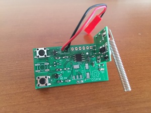
After the last two posts, I decided to build a simple PCB to handle various remotes in a single device and also serve as a “general purpose keyfob”. I’ve built it around a PIC12F1840 microcontroller which I had handy. This microcontroller includes an internal oscillator so the external components were reduced to a minimum: just the radio transmitter, some push-buttons and a LED.

remote-sch

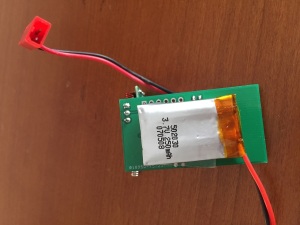
Initially, I aimed to power the board directly from a 1-cell Lipo battery (or 3 AA/AAA) but I included support for a higher voltage supply just in case the transmission power was too weak. If you want to power the keyfob with a higher voltage, just solder the regulator and adjust the resistors (R1, R3 and R5) so that the PIC reads no more than VCC volts at its inputs. For my application, it works just fine with a 4.2 battery and I get around 30 meters of transmission distance.

The board remains unpowered until the user presses a button. At that time, the microcontroller boots up, reads which of the button’s been pressed and executes the action until released. Theoretically, a single battery should last a few years.

Below you can download the Kicad files so that you can modify anything, as well as the gerber files to order it your own. The transmission module can be easily found on many sites for less than $2.

Keyfob KICAD Files

Keyfob GERBER Files

Below is the C code for the microcontroller that can be compiled using the free version of MPLAB IDE. It’s an example of how to send a different command depending on which button is pressed by the user.

/* 
 * File:   main.c
 * Author: Dani
 *
 * Created on 7 de marzo de 2016, 20:06
 */

#include <stdio.h>
#include <stdlib.h>

#include <xc.h>

#define _XTAL_FREQ 16000000 

// #pragma config statements should precede project file includes.
// Use project enums instead of #define for ON and OFF.

// CONFIG1
#pragma config FOSC = INTOSC    // Oscillator Selection (INTOSC oscillator: I/O function on CLKIN pin)
#pragma config WDTE = OFF       // Watchdog Timer Enable (WDT disabled)
#pragma config PWRTE = OFF      // Power-up Timer Enable (PWRT disabled)
#pragma config MCLRE = ON       // MCLR Pin Function Select (MCLR/VPP pin function is MCLR)
#pragma config CP = OFF         // Flash Program Memory Code Protection (Program memory code protection is disabled)
#pragma config CPD = OFF        // Data Memory Code Protection (Data memory code protection is disabled)
#pragma config BOREN = ON       // Brown-out Reset Enable (Brown-out Reset enabled)
#pragma config CLKOUTEN = OFF   // Clock Out Enable (CLKOUT function is disabled. I/O or oscillator function on the CLKOUT pin)
#pragma config IESO = ON        // Internal/External Switchover (Internal/External Switchover mode is enabled)
#pragma config FCMEN = ON       // Fail-Safe Clock Monitor Enable (Fail-Safe Clock Monitor is enabled)

// CONFIG2
#pragma config WRT = OFF        // Flash Memory Self-Write Protection (Write protection off)
#pragma config PLLEN = ON       // PLL Enable (4x PLL enabled)
#pragma config STVREN = ON      // Stack Overflow/Underflow Reset Enable (Stack Overflow or Underflow will cause a Reset)
#pragma config BORV = LO        // Brown-out Reset Voltage Selection (Brown-out Reset Voltage (Vbor), low trip point selected.)
#pragma config LVP = ON         // Low-Voltage Programming Enable (Low-voltage programming enabled)

/*
 * 
 */


/* 
 * RA0 = S1 (INPUT) LEFT
 * RA1 = S2 (INPUT) INH
 * RA2 = S3 (INPUT) RIGHT
 * RA5 = Tx (OUTPUT)
 * 
 * RA4 = Testpoint
 * 
 */

#define TX_PIN  RA5

#define PKT_LENGTH  48

const unsigned char left_pkt[]   = {0x00,0x00,0x00,0x00,0xAA,0x00,0x00,0x00,0xAA,0xAA,0xAA,0xAA,0x00,0x00,0x00,0x00,0xAA,0x00,0x00,0x00,0xAA,0xAA,0xAA,0xAA,0x00,0x00,0x00,0x00,0xAA,0x00,0x00,0x00,0xAA,0xAA,0xAA,0xAA,0x00,0x00,0x00,0x00,0xAA,0x00,0x00,0x00,0xAA,0xAA,0xAA,0xAA};
const unsigned char right_pkt[]  = {0x00,0x00,0x00,0x00,0xAA,0x00,0x00,0x00,0xAA,0xAA,0xAA,0xAA,0x00,0x00,0x00,0x00,0xAA,0x00,0x00,0x00,0xAA,0xAA,0xAA,0xAA,0x00,0x00,0x00,0x00,0xAA,0x00,0x00,0x00,0xAA,0xAA,0xAA,0xAA,0x00,0x00,0x00,0x00,0xAA,0xAA,0xAA,0xAA,0x00,000,0x00,0x00};

#define BITDELAY    70

#define delayMicroseconds   __delay_us
void tx_frame(const unsigned char *ptr, unsigned int length)
{
    unsigned int i;
    for(i=0;i<length;i++)
    {
        
        TX_PIN = ((ptr[i] & 0x80) != 0);    delayMicroseconds(BITDELAY);
        TX_PIN = ((ptr[i] & 0x40) != 0);    delayMicroseconds(BITDELAY);
        TX_PIN = ((ptr[i] & 0x20) != 0);    delayMicroseconds(BITDELAY);
        TX_PIN = ((ptr[i] & 0x10) != 0);    delayMicroseconds(BITDELAY);
        TX_PIN = ((ptr[i] & 0x08) != 0);    delayMicroseconds(BITDELAY);
        TX_PIN = ((ptr[i] & 0x04) != 0);    delayMicroseconds(BITDELAY);
        TX_PIN = ((ptr[i] & 0x02) != 0);    delayMicroseconds(BITDELAY);
        TX_PIN = ((ptr[i] & 0x01) != 0);    delayMicroseconds(BITDELAY);
    }
    __delay_ms(20);
}


int main(int argc, char** argv)
{
  unsigned char left=0, right=0, extra=0;
  
  OSCCON |= (0x0F<<3);  // Internal oscillator @ 16MHz
  
  ANSELA = 0;                       // No analog inputs 
  WPUA=0;                           // No internal pullups
  TRISA |= ((1<<0)|(1<<1)|(1<<2));  // Buttons as Inputs
  TRISA &= ~(1<<4);                 // RA4 (testpoint) as Output PIN
  
  RA4=0;

  // Allow some time to set things up
  __delay_ms(100); 
    
  //Check what actions are requested:
  if((PORTA & 1) == 1)  left    = 1;
  if((PORTA & 2) == 2)  extra   = 1;
  if((PORTA & 4) == 4)  right   = 1;
  
  while(1)
  {
      if(left==1)
          tx_frame(left_pkt,PKT_LENGTH);
      if(right==1)
          tx_frame(right_pkt,PKT_LENGTH);
  }
        
  return (EXIT_SUCCESS);
}

Below, a couple of pictures of the board with the transmission module attached:

IMG_7743

IMG_7744


I’ll build a second version of the board to fit a 3-button case or maybe I get one case 3D printed 🙂


RFCat, TI Chronos and replaying RF signals :)

After my first contact with the RTL-SDR a couple of days ago , I’ve been researching a bit more and found this fantastic blog post by Adam Laurie which describes how to use a TI Chronos development kit to send arbitrary sub-1GHz signals. It happens that I had such a kit so I decided to emulate another garage door opener, but this time using RFCat.

Loading RFCat firmware into the Chronos USB Dongle

First thing I did was to flash the USB dongle with the RFCat firmware so that I could emulate the remote from a python script. As I had a CC Programmer handy (you can also use GoodFET), I wired it up by following the diagram below and flashed the RFCat bin for the ez Chronos dongle using the SmartRF Flash Programmer tool.

ez_jtag_diagram


ez_jtag

ez_rfcat

ez_hack2

You can either flash the dongle with the RFCat binary itself or with the CC Bootloader which will allow you to update the dongle further without having to use the JTAG. I took the second approach so after flashing the bootloader, you’ll need to flash the actual RFCat firmware:

python bootloader.py /dev/ttyACM0 download RfCatChronosCCBootloader-150225.hex

After successfully flashing the dongle, it should show up as “RFCat” and you should be able to communicate with it from the rfcat interpreter:

RFCat_enumRFCat_r

As the communication with the dongle was good, it was time to analyze the signal sent by the remote and write some code to replay it using RFCat.

Signal Analysis

For the analysis part, I used the SDR# tool for Windows: tuned the right frequency (433.92MHz) and saved the signal into a Wav file for later analysis with Audacity.

audacity_ref1_mod

It’s a fixed code and looks pretty straightforward: short and long pulses. We can estimate the length of each type by measuring the number of samples. In this case, short pulses took 3000 samples or 1200us (sample rate was 2.4Ms on SDRSharp).

A good way to represent the signal is to encode the “long pulse plus silence” as “1” and the “short pulse plus silence” as “0”. Then, the frame would look like this:

1  0  1  1  0  1  1  1  1  1  1  0  0  0  0  0  1  0  1  1  0  0  1  1  0  0  1  1  0  0  1  1  1

As the “1” is formed by two high and one low short pulses of equal duration, we can express it as “110”. Similarly, our “0” can be represented as “100” and the frame now would be:

110 100 110 110 100 110 110 110 110 110 110 100 100 100 100 100
110 100 110 110 100 100 110 110 100 100 110 110 100 100 110 110 110

However, if we zoom in on the signal, we can see that the pulses are divided in more little pulses that we’ll need to encode in some way:

audacity_ref2

So, the final frame would make us rewrite the previous one changing every “1” bit by \xAA\xAA  and every “0” bit by \x00\x00 to maintain the length of each bit (see code below).  The duration of each bit is now about 80 us.

Replaying signal with RFCat

Now that we have analyzed the signal, it’s time to write a Python script to interface the RFCat dongle so that it generates the frames accordingly. Afterwards, we’ll capture the signal back to make sure that both the waveform and timing are correct:

from rflib import*
from time import sleep

pkt = '\xAA\xAA\xAA\xAA\x00\x00\xAA\xAA\x00\x00\x00\x00\xAA\xAA\xAA\xAA\x00\x00\xAA\xAA\xAA\xAA\x00\x00\xAA\xAA\x00\x00\x00\x00\xAA\xAA\xAA\xAA\x00\x00\xAA\xAA\xAA\xAA\x00\x00\xAA\xAA\xAA\xAA\x00\x00\xAA\xAA\xAA\xAA\x00\x00\xAA\xAA\xAA\xAA\x00\x00\xAA\xAA\xAA\xAA\x00\x00\xAA\xAA\x00\x00\x00\x00\xAA\xAA\x00\x00\x00\x00\xAA\xAA\x00\x00\x00\x00\xAA\xAA\x00\x00\x00\x00\xAA\xAA\x00\x00\x00\x00\xAA\xAA\xAA\xAA\x00\x00\xAA\xAA\x00\x00\x00\x00\xAA\xAA\xAA\xAA\x00\x00\xAA\xAA\xAA\xAA\x00\x00\xAA\xAA\x00\x00\x00\x00\xAA\xAA\x00\x00\x00\x00\xAA\xAA\xAA\xAA\x00\x00\xAA\xAA\xAA\xAA\x00\x00\xAA\xAA\x00\x00\x00\x00\xAA\xAA\x00\x00\x00\x00\xAA\xAA\xAA\xAA\x00\x00\xAA\xAA\xAA\xAA\x00\x00\xAA\xAA\x00\x00\x00\x00\xAA\xAA\x00\x00\x00\x00\xAA\xAA\xAA\xAA\x00\x00\xAA\xAA\xAA\xAA\x00\x00\xAA\xAA\xAA\xAA\x00\x00'

NUM_REPS	= 10		# times the frame will be sent
DELAY 		= 0.02	# seconds between frames

try:

	d = RfCat()
	d.setMdmModulation(MOD_ASK_OOK)
	d.setFreq(433290000)	# Set freq to 433.92MHz
	d.setMaxPower()
	d.setMdmSyncMode(0)		# Don't send preamble/sync word
	d.setMdmDRate((int)(1.0/0.000080))	# Our bits are 80us long
 	d.makePktFLEN(len(pkt))

	print "Sending frames "
	for i in range(0,NUM_REPS):
		sys.stdout.write(".")
		d.RFxmit(pkt)
		sleep(DELAY)
	print " Done\n"
	d.setModeIDLE()

except Exception, e:
	sys.exit("Error %s" % str(e))

Now let’s run the script and capture the signal back with SDR# to check if it looks like it should:

audacity_ref_captured1_mod

audacity_captured_zoom1

The first picture shows both our reference signal (sent by the remote) and the one generated with the RFCat dongle. The second picture shows the detail of each bit. As expected, it opened the door although the output power seemed a bit too low . Maybe there’s a hack to improve the antenna of the Chronos dongle?  🙂

Replaying the signal with the Chronos Sports Watch

Okay, the hard part is over so let’s have some fun and replay the signal directly from our wrist 🙂

The ChronIC project is pretty much like the RFCat firmware but can loaded directly into the Chronos Sports Watch so that pre-loaded signals can be sent just by pressing the up/down buttons. I modified the code to make the watch send our frame every time I pressed the UP button. Below is the code that will do the magic, and a couple of useful Python functions (from Adam’s code) to calculate the register values for your bitrate and frequency:


 def setfreq(freq):
	mhz= 26
	freqmult = (0x10000 / 1000000.0) / mhz
	num = int(freq * freqmult)
	freq0= num & 0xff
	payload= chr(freq0)
	freq1= (num >> 8) & 0xff
	payload += chr(freq1)
	freq2= (num >> 16) & 0xff
	payload += chr(freq2)
	print '- FREQ2: %02x FREQ1: %02x FREQ0: %02x -' % (freq2, freq1, freq0)

def setdatarate(drate):
	mhz= 26
	drate_e = None
	drate_m = None
	for e in range(16):
		m = int((drate * pow(2,28) / (pow(2,e)* (mhz*1000000.0))-256) + .5)        # rounded evenly
		if m < 256:
			drate_e = e
			drate_m = m
			break
	if drate_e is None:
		return False, None
	drate = 1000000.0 * mhz * (256+drate_m) * pow(2,drate_e) / pow(2,28)
	print 'drate_e: %02x  drate_m: %02x' %(drate_e,drate_m)
void config_garage(u8 line)
{
	// gap between data pulses
	//Button_Delay= 0;
	Button_Delay= 20;
	// how many times to send per button press
	Button_Repeat= 10;

	// set button content

	Up_Buttons= 1;
	// packet length
	Button_Up_Data[0][0]= 198;
	// payload
	memcpy(&Button_Up_Data[0][1],"\xAA,\xAA,\xAA,\xAA,\x00,\x00,\xAA,\xAA,\
 \x00,\x00,\x00,\x00,\xAA,\xAA,\xAA,\xAA,\x00,\x00,\xAA,\xAA,\xAA,\xAA,\x00,\x00,\
 \xAA,\xAA,\x00,\x00,\x00,\x00,\xAA,\xAA,\xAA,\xAA,\x00,\x00,\xAA,\xAA,\xAA,\xAA,\
 \x00,\x00,\xAA,\xAA,\xAA,\xAA,\x00,\x00,\xAA,\xAA,\xAA,\xAA,\x00,\x00,\xAA,\xAA,\
 \xAA,\xAA,\x00,\x00,\xAA,\xAA,\xAA,\xAA,\x00,\x00,\xAA,\xAA,\x00,\x00,\x00,\x00,\
 \xAA,\xAA,\x00,\x00,\x00,\x00,\xAA,\xAA,\x00,\x00,\x00,\x00,\xAA,\xAA,\x00,\x00,\
 \x00,\x00,\xAA,\xAA,\x00,\x00,\x00,\x00,\xAA,\xAA,\xAA,\xAA,\x00,\x00,\xAA,\xAA,\
 \x00,\x00,\x00,\x00,\xAA,\xAA,\xAA,\xAA,\x00,\x00,\xAA,\xAA,\xAA,\xAA,\x00,\x00,\
 \xAA,\xAA,\x00,\x00,\x00,\x00,\xAA,\xAA,\x00,\x00,\x00,\x00,\xAA,\xAA,\xAA,\xAA,\
 \x00,\x00,\xAA,\xAA,\xAA,\xAA,\x00,\x00,\xAA,\xAA,\x00,\x00,\x00,\x00,\xAA,\xAA,\
 \x00,\x00,\x00,\x00,\xAA,\xAA,\xAA,\xAA,\x00,\x00,\xAA,\xAA,\xAA,\xAA,\x00,\x00,\
 \xAA,\xAA,\x00,\x00,\x00,\x00,\xAA,\xAA,\x00,\x00,\x00,\x00,\xAA,\xAA,\xAA,\xAA,\
 \x00,\x00,\xAA,\xAA,\xAA,\xAA,\x00,\x00,\xAA,\xAA,\xAA,\xAA,\x00,\x00",Button_Up_Data[0][0]);

	Down_Buttons= 0;

	// set frequency (433920000)
	ChronicRF.freq0= 0x71;
	ChronicRF.freq1= 0xB0;
	ChronicRF.freq2= 0x10;

	// set data rate (pulsewidth 80us)
	// drate_m
	ChronicRF.mdmcfg3= 0xf8;
	// drate_e
	ChronicRF.mdmcfg4 &= 0xf0;
	ChronicRF.mdmcfg4 |= 8;

	// set modulation
	ChronicRF.mdmcfg2 &= ~MASK_MOD_FORMAT;
	ChronicRF.mdmcfg2 |= MOD_OOK;
	// set sync mode
	ChronicRF.mdmcfg2 &= ~MASK_SYNC_MODE;
	ChronicRF.mdmcfg2 |= SYNC_MODE_NONE;
	// set manchester false
	ChronicRF.mdmcfg2 &= ~MASK_MANCHESTER;
	display_symbol(LCD_ICON_RECORD, SEG_ON);
	Emulation_Mode= EMULATION_MODE_GARAGE;
}

After  building the code with Code Composer and loading it into the Watch with the JTAG included in the kit, a new menu is available and the signal’s going to be sent every time we press the UP button.

ez_menu

🙂 🙂

All the information in this blog is for educational  purposes only.  You shall not misuse the information to gain unauthorized access.