Disclaimer: All the information posted is intended for illustrative and educational purposes only. I just want to show you that it’s possible to set up the iPhone SDK on a Virtual Machine. Please, BUY an Apple Mac OS X License if you are going to use this and BUY a Mac computer (Apple’s EULA agreement states that you cannot run Mac OS X under non Apple hardware).
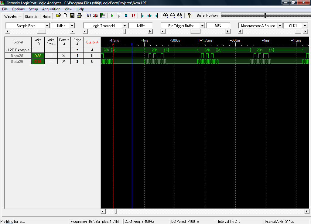
In this post I will try to explain how to set up the SDK for iPhone OS 3.1 on a PC running Windows (Vista 64 in my case). From the readme file of the SDK you can read:
Xcode 3.1.4, when used for Mac-only development, is compatible with Intel and PowerPC Macs running Mac OS X Leopard 10.5 and later. Use of the iPhone SDK requires an Intel-based Mac running Mac OS X Leopard version 10.5.7 or later.
So we need a Leopard 10.5. By googling a little bit you will realize that there are some modified ready-to-use Leopard images out there that you can download and run out of the box on VMWare.
I’m running a 10.5.2 version (which takes about 5 mins to boot on my quad core). Once you get a Mac OS X running on your PC, you can download the free iPhone SDK from developer.apple.com and install it.
The iPhone SDK for OS 3.1 won’t install under a version prior to 10.5.7 so I had to ‘trick’ the installer rather to update the Mac OS X which seems to be a painful process. To do this, you have to modify the /System/Library/Core Services/SystemVersion.plist and change both the ProductUserVisibleVersion and ProductVersion keys to 10.5.7.
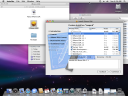
With this done, I selected just the SDK for 3.1 (to save space in my hard disk) and the installation process begins.
 And 3.5 hours later….
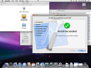
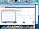
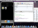
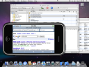
Once you have the iPhone SDK installed, you can run Xcode (from SpotLight) and launch a new project using a template just to try it out on the iPhone Simulator:
At this point you can develop your own iPhone applications and test them on the simulator. Also, if you joined the Apple developer program (the standard one is $99) you can test them in your iPhone as well.
If you’re planning to play around with the SDK I strongly recommend you to sign up on the iPhone Dev Center because there are lots of resources available: Getting started documents, videos, sample code, etc.
More to come,
Daniel