I want to show you how easy is to start playing around with FPGAs. The following example is based on the Actel A3P250 Devel board programmed with the microJTAG board.
The idea is simple: we’re going to design a PWM module and make the on-board leds flashing at different rates. The RTL design of the PWM module is shown in the picture below:
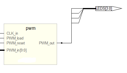
Let’s have a look at the components inside the PWM module:
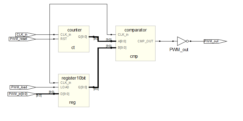
As you can see the 10-bit PWM module has got one register, a 10-bit counter and one comparator. To test our module, I’ll write a simple VHDL code:
-- test.vhd
library IEEE;
use IEEE.STD_LOGIC_1164.ALL;
use IEEE.STD_LOGIC_ARITH.ALL;
use IEEE.STD_LOGIC_UNSIGNED.ALL;

entity example2 is
    Port (

                LEDS:out STD_LOGIC_VECTOR(3 downto 0);
                CLK_in: in STD_LOGIC;
                RESET_in: in STD_LOGIC

           );
end example2;

architecture Behavioral of example2 is

component pwm is
    Port (

        CLK_in:     in std_logic;
        PWM_in:     in std_logic_vector(9 downto 0);
        PWM_load:   in std_logic;
        PWM_reset:  in std_logic;
        PWM_out :   out std_logic

        );
end component;

      signal counter: natural range 0 to 48000;
      signal result: STD_LOGIC_VECTOR (9 downto 0);
      signal pwmout: STD_LOGIC;
      signal clk_div: std_logic;

begin

    pwm1 : pwm port map ( CLK_in => CLK_in, PWM_in => result,
 PWM_load => '1', PWM_reset => not RESET_in,
 PWM_out => pwmout);

   process(CLK_in,RESET_in,counter)
    begin
         if (RESET_in='0') then

            counter <= 0;
            clk_div <= '0';

        elsif (CLK_in'event and CLK_in='1')    then

            if (counter = 47999) then
                clk_div <= not clk_div;
                counter <= 0;
            else
               counter <= counter + 1;

            end if;
        end if;

    end process;

    process(clk_div, result)
    begin
        if (clk_div'event and clk_div='1')    then
            result <= result + 1;
        end if;

    end process;

    LEDS <= (others => pwmout);

end Behavioral;
The frequency divider makes the ‘result’ signal increment every 48K*2 ticks of the main clock (24MHz). The ‘result’ signal is connected to the input of the PWM module which will load its value every time it changes because the LOAD signal is always ‘1’.
The result will be that every 4ms, the PWM input will increment by 1 from 0 to 1023 (10 bit value). The PWM output – which is connected to all LEDs in the board – will take all values after 4 seconds and the cycle will repeat continuously.
You can download the whole source code from the link below:
The A3P250 Devel kit was a present from my friend Ajo and I want to thank him for such a nice board 🙂
Daniel