I’ve never liked to use an external hardware to program microcontrollers, so one of the reasons to choose the LPC1343 microcontroller for the uXbot robot was its internal USB MSC bootloader which enables users to download their firmwares by dragging & dropping files into a flash drive. However, when you’re working in your robot, sometimes it’s a pain to pick it up and plug it to the PC, specially when you’re a lazy engineer 🙂 so here I want to introduce you a tiny Bluetooth Bootloader for the uXbot robot.
As you can see, the bootloader resides at the end of the flash memory and whenever the user code jumps into it, it copies itself to RAM before starting the flashing process. This way, the bootloader can also be updated from the bootloader itself 🙂 In the video below you can see a demo of the bootloader in action. From the uXbot Manager PC application the firmware is downloaded into the robot’s memory (via Bluetooth, of course) and the new code can start running right after the process is completed (less than 2 seconds to download a ~2KB firmware). The user code jumps into the bootloader whenever the button is pressed but the application can enter the bootloader remotely or by any other means.
One of the things I’ve found more interesting and useful in Robotics is debugging.
Most of the time we use to print out traces through a serial port and, the luckiest ones, who own a JTAG emulator, can dig deeper into their bugs but always with a cable plugged.
So, now thanks to the excellent Espardino project and the help of its author, Ajo, who is a very good friend of mine, I decided to write my own stub for the ARM cortex-m3 architecture. You can check out more information about Espardino’s remote monitor here.
Also, the following are a nice source of information I used to write this stub:
Daniel Jacobwitz patch for the Linux Kernel – single stepping Thumb2 programs
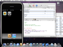
The video below shows a debugging session of the stub running inside the LPC1343 ARM Cortex-M3 of the uXbot robot. The GDB is connected to a tiny application which acts as a bridge between the TCP connection and the bluetooth link to the robot. Given that this application is listening on a TCP port, the GDB debugger can be running somewhere else (on my iPhone? ;)) and it would still work.
In my next article I will get more into detail about the stub itself and the exception handling.
SPI (Serial Peripheral Interface) protocol is a synchronous serial data link which operates in full duplex mode. It’s got a higher throughput compared to I2C or SMBus and it’s very useful for high speed short-range communications.
The SPI protocol specifies the following signals:
SCLK — Serial Clock (output from master)
MOSI/SIMO — Master Output, Slave Input (output from master)
MISO/SOMI — Master Input, Slave Output (output from slave)
SS — Slave Select (active low, output from master)
All lines can be shared for every slave device in the bus except the Slave Select signal which has to be different (out of band selection) for each slave.
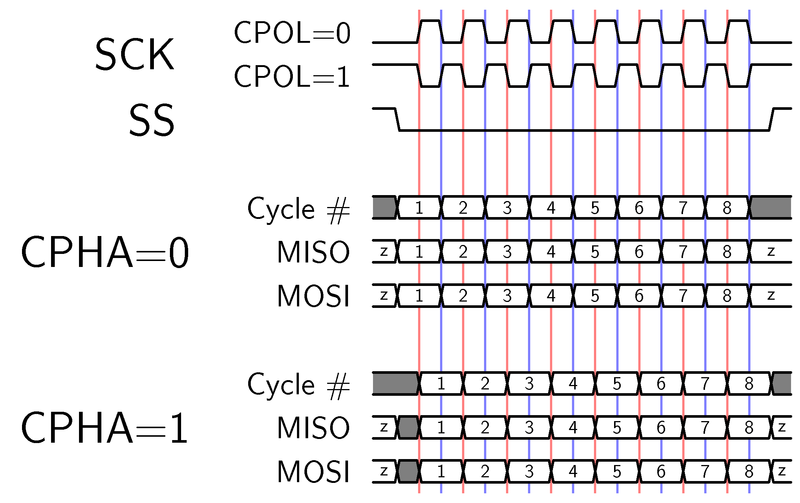
This is the basic operation depending on the CPOL and CPHA values:
The SPI core I’ve implemented is fixed for Slave and CPOL=0/CPHA=0 modes. This means that the MOSI line will be sampled at every rising edge of the SPI Clock whilst the MISO signal will be set right before this rising edge (actually, on the falling edge) so that it can be properly sampled by the Master.
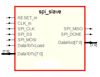
As the FPGA will have its own clock, we’ll be having two different clock domains since the SPI master signals will be generated externally and they won’t be necessarily synchronized to the FPGA internal clock. Thus, the approach will be sampling all the external signals to get them synchronized and using two shift registers for input and output data.
Source code:
entity spi_slave is
  port (
    RESET_in    : in  std_logic;
    CLK_in      : in  std_logic;
    SPI_CLK     : in std_logic;
    SPI_SS      : in std_logic;
    SPI_MOSI    : in  std_logic;
    SPI_MISO    : out std_logic;
    SPI_DONE    : out std_logic;
    DataToTx    : in std_logic_vector(7 downto 0);
    DataToTxLoad: in std_logic;
    DataRxd     : out std_logic_vector(7 downto 0)
    );
end spi_slave;

architecture Behavioral of spi_slave is

    signal SCLK_latched, SCLK_old : std_logic;
    signal SS_latched, SS_old : std_logic;
    signal MOSI_latched: std_logic;
    signal TxData : std_logic_vector(7 downto 0);
    signal index: natural range 0 to 7;
    signal RxdData : std_logic_vector(7 downto 0);

begin

 --
 -- Sync process
 --

  process(CLK_in, RESET_in)

 begin
    if (RESET_in = '1') then
      RxdData  '0');
      index <= 7;
      TxData  '0');
      SCLK_old <= '0';
      SCLK_latched <= '0';
      SS_old <= '0';
      SS_latched <= '0';
      SPI_DONE <= '0';
      MOSI_latched <= '0';

    elsif( rising_edge(CLK_in) ) then

      SCLK_latched <= SPI_CLK;
      SCLK_old <= SCLK_latched;
      SS_latched <= SPI_SS;
      SS_old <= SS_latched;
      SPI_done <= '0';
      MOSI_latched <= SPI_MOSI;

      if(DataToTxLoad = '1') then
          TxData <= DataToTx;
      end if;

      if (SS_old = '1' and SS_latched = '0') then
          index <= 7;
      end if;

      if( SS_latched = '0' ) then
         if(SCLK_old = '0' and SCLK_latched = '1') then
            RxdData <= RxdData(6 downto 0) & MOSI_latched;
            if(index = 0) then -- cycle ended
               index <= 7;
            else
               index <= index-1;
            end if;
         elsif(SCLK_old = '1' and SCLK_latched = '0') then
            if( index = 7 ) then
               SPI_DONE <= '1';
            end if;
            TxData <= TxData(6 downto 0) & '1';
         end if;
      end if;
     end if;
   end if;
   end process;

   --
   -- Combinational assignments
   --

   SPI_MISO <= TxData(7);
   DataRxd <= RxdData;

end Behavioral;
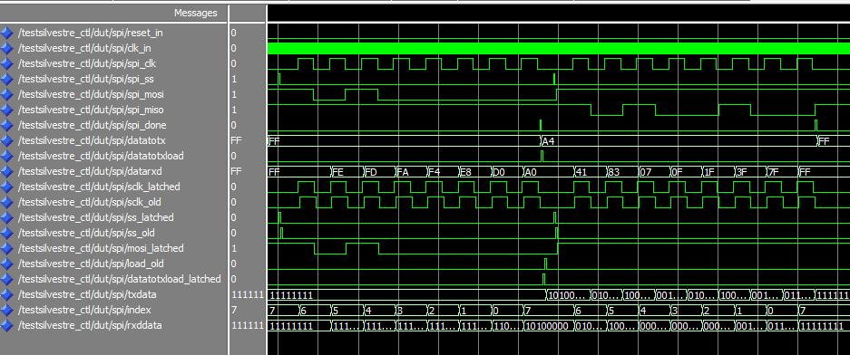
In order to test this core I wrote a simple testbench wich basically waits for a command from the master and answers it. This will serve as a base for the microcontroller code which will send this same command (0xA0) and wait for the answer (0xA4). This is the simulation view:
As you can see, when the spi_done signal goes high, the datarxd register is loaded with the value 0xA0. Afterwards, the answer to this command (0xA4) is loaded into the datatoxload register and the MISO line is set to the right bit at every falling edge of the SPI clock signal.
As the simulation looks good, I decided to wire up the FPGA to an LPC2148 microcontroller and test the SPI core for real. The following code will run in the LPC:
void send_fpga_cmd(unsigned char cmd)
{
    unsigned char dummy;
    IO0PIN &= ~(1<<11);    // Select FPGA
    while ( !(SSPSR & 0x02) );
    SSPDR=(unsigned int) cmd;
    while((SSPSR & (1<<4)));
    IO0PIN |= (1<<11);    // deselect FPGA
    dummy = SSPDR;         //flush the RxFIFO

}

unsigned char read_fpga_byte()
{
    unsigned char data;
    SSPDR= 0xFF;         // write dummy data out to gen clock
    while((SSPSR & (1<<4)));
    data = SSPDR;
    return data;
}

while(1)
{
    send_fpga_cmd(0xA0);
    data = read_fpga_byte();
}
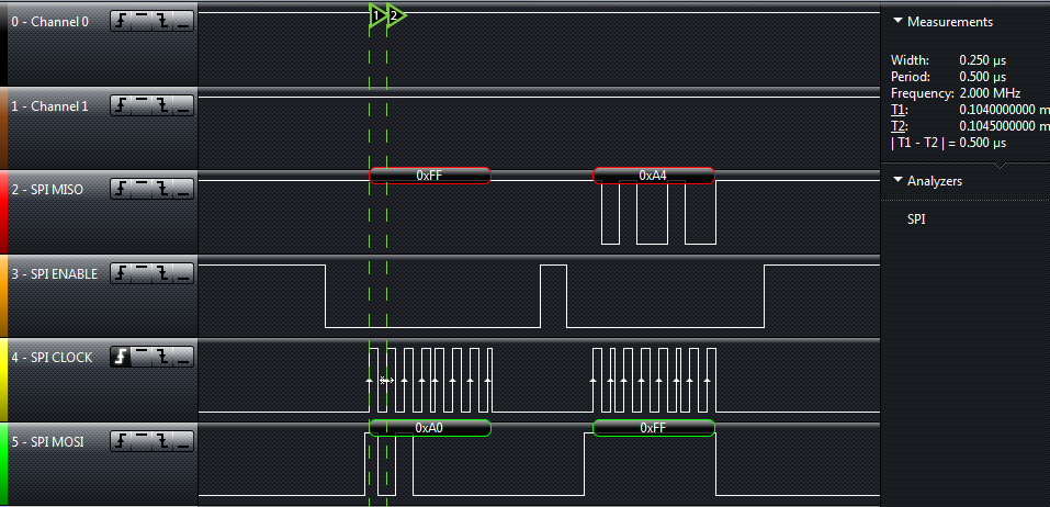
I configured the SPI bus to run at 2MHz on the microcontroller. Here you can see the logic analyzer output which shows that the SPI core works as expected.
As you can see, the microcontroller sends a ping (0xA0 byte) and the FPGA answers with a response command (0xA4 byte). The SPI clock frequency is exactly 2.000MHz and the behavior is the expected one.
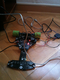
I want to show you how easy is to start playing around with FPGAs. The following example is based on the Actel A3P250 Devel board programmed with the microJTAG board.
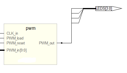
The idea is simple: we’re going to design a PWM module and make the on-board leds flashing at different rates. The RTL design of the PWM module is shown in the picture below:
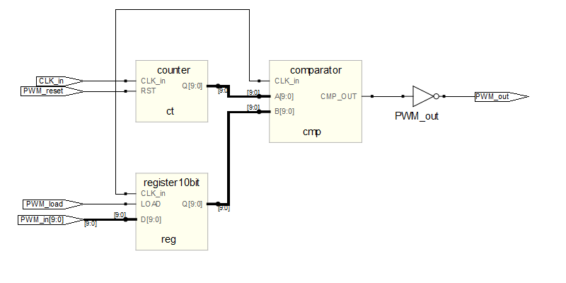
Let’s have a look at the components inside the PWM module:
As you can see the 10-bit PWM module has got one register, a 10-bit counter and one comparator. To test our module, I’ll write a simple VHDL code:
-- test.vhd
library IEEE;
use IEEE.STD_LOGIC_1164.ALL;
use IEEE.STD_LOGIC_ARITH.ALL;
use IEEE.STD_LOGIC_UNSIGNED.ALL;

entity example2 is
    Port (

                LEDS:out STD_LOGIC_VECTOR(3 downto 0);
                CLK_in: in STD_LOGIC;
                RESET_in: in STD_LOGIC

           );
end example2;

architecture Behavioral of example2 is

component pwm is
    Port (

        CLK_in:     in std_logic;
        PWM_in:     in std_logic_vector(9 downto 0);
        PWM_load:   in std_logic;
        PWM_reset:  in std_logic;
        PWM_out :   out std_logic

        );
end component;

      signal counter: natural range 0 to 48000;
      signal result: STD_LOGIC_VECTOR (9 downto 0);
      signal pwmout: STD_LOGIC;
      signal clk_div: std_logic;

begin

    pwm1 : pwm port map ( CLK_in => CLK_in, PWM_in => result,
 PWM_load => '1', PWM_reset => not RESET_in,
 PWM_out => pwmout);

   process(CLK_in,RESET_in,counter)
    begin
         if (RESET_in='0') then

            counter <= 0;
            clk_div <= '0';

        elsif (CLK_in'event and CLK_in='1')    then

            if (counter = 47999) then
                clk_div <= not clk_div;
                counter <= 0;
            else
               counter <= counter + 1;

            end if;
        end if;

    end process;

    process(clk_div, result)
    begin
        if (clk_div'event and clk_div='1')    then
            result <= result + 1;
        end if;

    end process;

    LEDS <= (others => pwmout);

end Behavioral;
The frequency divider makes the ‘result’ signal increment every 48K*2 ticks of the main clock (24MHz). The ‘result’ signal is connected to the input of the PWM module which will load its value every time it changes because the LOAD signal is always ‘1’.
The result will be that every 4ms, the PWM input will increment by 1 from 0 to 1023 (10 bit value). The PWM output – which is connected to all LEDs in the board – will take all values after 4 seconds and the cycle will repeat continuously.
You can download the whole source code from the link below:
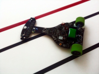
Last 8th October took place the 3rd edition of the CRJET International Robotics Competition in Cataluña.
Silvestre was the WINNER of the Line Following Robots category. During the qualifying session in the morning, Silvestre set the fastest time, completing 3 laps to the 11.752 meters track in 14.02 seconds (2.5m/s average speed). Piolin – Silvestre’s little brother – made the second best time at qualifying but had some issues and got a final 3rd place losing against Shibuya in the Semifinal round.
Its revolutionary positioning system allowed Silvestre to identify the main straight and to speed up to 4.8 m/s. Thanks to its inertial sensors and the wheel encoders, Silvestre could brake at the right point reaching the corner at a safe speed. This strategy had not been seen in any Line Follower competitions so far making Silvestre look even more impressive.
Silvestre Highlights (the slow motion part is very cool 😉 )
Final Race, Silvestre VS Shibuya:
For the next contests, the challenge is to make another key improvement to keep Silvestre on the top of the podium.
Also, Tobias was awarded with the “Most High-Tech” prize in the “Best of Show” category so it was a pretty successful weekend 🙂
Silvestre is a line following robot who was born early this year. So far, he’s competed in two national contests in Spain achieving a 5th place in the first one and winning the other one.Among his main features:
8 Infrared sensors
Two Maxon DC motors
Bluetooth enabled (telemetry and configuration)
LPC2148 ARM7 32-bit microcontroller
PD Loop running at 100Hz
Error estimation using cubic interpolation over the IR sensors data
Accelerometer and gyro sensors
In the video above you can see Silvestre running on a 8.44m long track. Whenever he crosses the mark, sends the lap time over the Bluetooth link to a PC software which displays the timing information along with some other data such as battery level. In the best lap in the video he can reach up to 2.24m/s and as long as the wheels become dirty, the grip decreases and therefore, the times get worse.
The microcontroler’s got 512KB the flash. Half of this memory’s currently holding a custom filesystem to store configuration profiles (speed, PID constants, enabling/disabling features, etc.) which can be loaded, stored and deleted through the PC software.
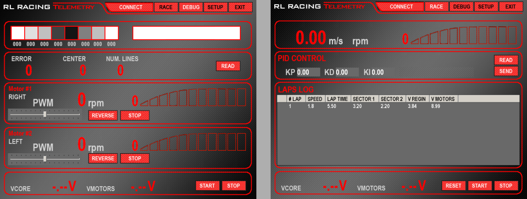
In order to speed up the communication between the computer and the robots we designed a low bandwith binary protocol with error correction which’s been implemented and optimized carefuly in all of our robots. This way, the development of new software (for both robot and computer side) gets simplified from the communication point of view and there’s no need to start over again every time. You can see an screenshot of the PC application we’ve built:
RL-Telemetry application
The inertial sensors help Silvestre to measure how good he’s performing and enables him to adjust the speed and PID constants as the wheels are losing grip. Basically, the accelerometer data is used to accelerate faster to the setpoint speed whereas the gyro tells him whether he starts drifting (too much angular acceleration).
In the contests being held in Spain, there are no marks indicating when a lap has started so there’s no way for the robot to figure out when to modify its parameters so something that might be useful as well with the gyro data is to be aware of the actual orientation of the robot. Thus, integrating the gyro signal, Silvestre knows when he is facing the initial position again and this is likely the starting point. However, this approach is not valid when the track’s got two or more straights in the same direction because the robot will get to 360º and the lap’s not been completed yet.
The key for improving Silvestre’s performance has been undoubtely the ability to gather data from the sensors in real-time so that they can be later analysed on a computer.
My friend Alberto Calvo and me have worked hard on this robot and we’re looking forward for new contests and challenges. Our main goal, rather than just following a line, was researching how the usage of inertial sensors and self-learning processes could be applied on this kind of robots. We’re still working on Silvestre in our spare times so I’ll probably update this post soon.
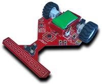
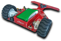
I want to introduce you the brand-new uXbot (micro xBot) robot. It has been designed for educational purposes and with the main goal of serving as a base for the Robotics Workshop at Campus-Party España 2010.
Features:
ARM Cortex-M3 32 bit Microcontroller (LPC1343)
Motor driver up to 3.5A
12 Infrared sensors
Integrated battery charger
Battery Voltage monitoring
Firmware Programming via USB
4 General Purpose LEDs
800mAh Li-Po battery
Metal Gearbox motors
Bluetooth module
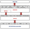
In order to make the development process easier, some libraries have been written for the end user with the following layout:
HALLib (Hardware Abstraction Layer Library): Provides an interface to uXbot hardware and the microcontroller peripherals such as sensor reading, pushbutton, voltage monitor, motors, timing functions.
VCOMLib: Provides a USB Virtual COM Port driver (ACM profile under Linux OS) so that the user can communicate to a PC.
uXbotLib: This is a high-level library which will be mainly used by users who do not have/need to have any knowledge about the underlying electronics of the uXbot. It provides an interface to move the robot in any direction, an open-loop PID controller for line following, sensor reading and filtering, etc.
All the tools used to develop applications for the uXbot are free and available for both Windows and Linux OS (32 and 64-bit).
In order to control the uXbot through the USB VCom port or Bluetooth, a C# application has been written. Anyone will be able to use it from Windows or Linux (using Mono). Here you can see an screenshot:
I want to show you two videos. In the first one you can see the uXbot being controlled from a Windows Mobile device using a simply C# application which sends commands to the motors depending upon the PDA acclerometer sensor readings. It’s pretty funny and addicting 🙂 In the second one, the uXbot is following a black line at an average speed of 1.65 meters per second.
I would like to publish all the source and diagrams soon, so stay tunned 🙂
Daniel
PS. You can find more information at www.uxbot.es (Wiki & Forum in Spanish).
I’ve been playing around with SMS PDUs encodings and recently observed some curious things regarding the way that cellphones treat the text messages when they include special characters.First look at these two tables of the GSM alphabet:
The tables above show the GSM Alphabet using a 7-bit encoding which implies a maximum number of 160 characters per text message. However, sometimes this is a little bit more tricky and the count is not so straightforward: If, for instance, you type a character from the second table, it needs to be escaped with the escape character 1) 0xB1, and it will take two characters instead of one. What happens if your text message contains 160 characters and one of them is a ‘]’? Simple: You will get charged for two text messages because you’re exceeding the maximum length of a simple PDU. Usually your cellphone won’t warn you about this and you will send it anyways without knowing the fact that this text message will cost twice than you think. The same happens with the ‘€’ symbol and some other not showing up in the table above.If you have a closer look at the tables, you might realize that the ‘é’ symbol appears but where are ‘á’,’í’,’ó’ and ‘ú’? The GSM alphabet was originally designed by France and they only use ‘é’ so if you want to use accents, there’s no way using this encoding. I have tested some cellphones and they behave in two different ways:
Removing those characters with accents (except ‘é’) and substituting them by the same character without accent.
Using a 16-bit UNICODE encoding to allow sending every character (in this case, the maximum length of the textmessage is 70 characters).
In case 1, the only ‘side-effect’ is that the recipient of the text message won’t get your accents and you can send up to 160 characters. In case 2, your cellphone won’t warn you and you might send up to 160 characters thinking that it will take just one text message.However, again, you will be charged for up to 3 text messages without knowing it! The recipient will get a multi-part message showing all the characters you sent with no modification. Here you can see the decoding of a PDU (using PDUSpy) of a text message sent with accents and encoded using UCS2:
PROTOCOL IDENTIFIER (0x00)
MESSAGE ENTITIES : SME-to-SME
PROTOCOL USED : Implicit / SC-specific
DATA CODING SCHEME (0x08)
AUTO-DELETION : OFF
COMPRESSION : OFF
MESSAGE CLASS : NONE
ALPHABET USED : 16bit UCS2
If the accents are removed from the original text message, the cellphone will automatically use the GSM7 alphabet and you will be allowed to send up to 160 characters in just one PDU (you will get charged once).All in all, be careful and if possible make some research to figure out what your cellphone does and check it against your bill because you will probably save some (or a lot of) money. Cheers, D.
Since the very first moment I saw a 2-wheel self-balancing robot I got amazed about all the engineering behind it and I was so excited to build one myself. So now that it’s become a reality let me introduce you to TOBIAS
Accelerometer: Slow response & sensitive to acceleration forces due to movement
Gyroscope: Fast response & integration drift for angle estimation
Need to mix up the information from both sensors: Kalman Filter
Kalman Filter:
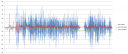
In this graphic you can see some data captured in real time by the microcontroller and then dumped offline to a PC for a later analysis.
The blue signal represents the estimated angle using just the raw data from the accelerometer: arc-tangent of y-axis by x-axis acceleration.
The green signal is the integration of the gyro sensor which clearly shows the drift over the time.
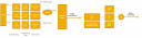
The red signal is the actual angle estimated by the Kalman Filter which shows that in the balancing state the angle falls between -3 and 3 degrees. Block Diagram:
Here you can see the block diagram of the complete system. First, you can observe that the signals are sampled at 3200Hz (oversampling) and then low-pass filtered with a Finite Impulse Response (FIR) Filter with a cutoff frequency of 100Hz.
A 16x decimator is then used to obtain signals with a bandwith of 200Hz and no aliasing. This filtering process improved the angle estimation so much because a lot of noise was removed.
The inputs for the Kalman Filter are the angular rate and the estimated angle from the accelerometer which is computed using an atan2 function call. After that, some tests reported that the angle output by the KF had a precision of about .1º which looks really accurate.
This angle is ready to be processed in order to apply the right torque to the motors using a PID controller -tunned by hand- with more effort than expected (and desired). The integral part of the PID is computed by the trapezoidal rule while the derivative component is calculated using a 7-steps Savitzky-Golay derivator.
The output of the PID is then applied to both motors in order to keep it balanced.
Implementation:
The LPC2148 is a very powerful 32-bit microcontroller which shouldn’t have many problems acting as TOBIAS’ brain. However, the firmware was as optimized as possible in order to allow future improvements and, in the mean time, keep the processor in power down mode while not doing anything to save battery (every mA of current counts ;)).
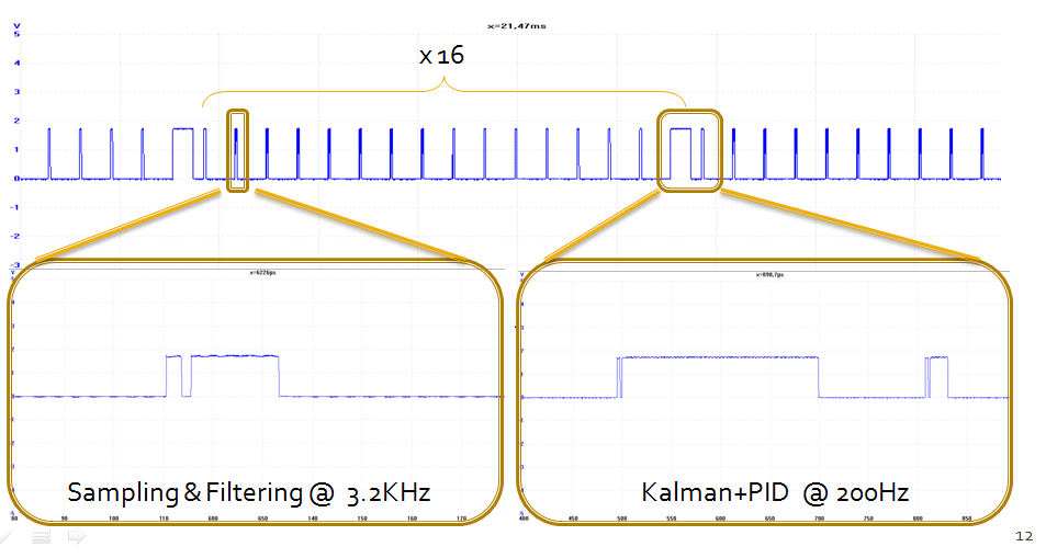
In order to figure out how the microcontroller could handle all the tasks, a profiling of the execution was performed using a GPIO and a logic analyzer:
As you can see from the image above, there’s plenty of time for the microcontroller to do some other things. This time was used mainly for logging purposes and in the current version, to read from a IR receiver and controlling TOBIAS using a cheap remote controller from an RC helicopter. This performance was achieved after optimizing the code of the most computationally expensive tasks (Kalman & PID). Also these functions execute from RAM and try to make a good use of the MAM (Memory Accelerator Module) hardware in order to speed its execution up as much as possible.
Considerations for future improvements:
The first approach was building a fairly good balancing robot without spending too much money and now I can say that it was definitely achieved.
The sensors used in the IMU were taken off a cheap PS3 gamepad bought on eBay, there’s no commercial electronic boards (entirely own design) – apart from the cheap step up/down DC-DC controller ($15) -, and both the plastic sheets and wheels are quite cheap and, thus, the overall cost of the robot doesn’t go beyond the 100€ ($140-$150).
However, the cheap motors made all the project a little bit more difficult (and challenging at the same time) than expected: they were not enough responsive and the gearbox wasn’t tight enough allowing you to turn the wheels freely about 3 degrees.
I’m sure that if another motors were used in TOBIAS, the performance would have been way better but it was more exciting to face the PID tunning and the signal processing under these ‘negative’ conditions.
References & Greetings:
T.O.B.B. Balancing Robot by Matthias Toussaint: I would like to thank Matthias so much for answering my e-mails and pointing me in the right direction with his unvaluable advice. All the signal processing was based on TOBB’s and the only main difference is that TOBB uses a very interesting complimentary filter (instead of Kalman) which works incredibly well as you can see in the video posted on his site. Thanks once again Matthias because I learnt a lot from you !!
Also big thanks to my friend Alberto Calvo, the co-author, who also made the 3D artwork shown in the article 😉
Final Result:
All in all, it’s been a very interesting project and, as a reward, TOBIAS won a prize in the Freestyle Robotics Contest at Campus Party ’09 last summer.
In this video you can see TOBIAS in action:
Disclaimer: All the information posted is intended for illustrative andeducational purposes only. I just want to show you that it’s possible to set up the iPhone SDK on a Virtual Machine. Please, BUY an Apple Mac OS X License if you are going to use this and BUY a Mac computer (Apple’s EULA agreement states that you cannot run Mac OS X under non Apple hardware).
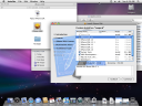
In this post I will try to explain how to set up the SDK for iPhone OS 3.1 on a PC running Windows (Vista 64 in my case). From the readme file of the SDK you can read:
Xcode 3.1.4, when used for Mac-only development, is compatible with Intel and PowerPC Macs running Mac OS X Leopard 10.5 and later. Use of the iPhone SDK requires an Intel-based Mac running Mac OS X Leopard version 10.5.7 or later.
So we need a Leopard 10.5. By googling a little bit you will realize that there are some modified ready-to-use Leopard images out there that you can download and run out of the box on VMWare.
I’m running a 10.5.2 version (which takes about 5 mins to boot on my quad core). Once you get a Mac OS X running on your PC, you can download the free iPhone SDK from developer.apple.com and install it.
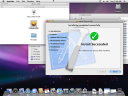
The iPhone SDK for OS 3.1 won’t install under a version prior to 10.5.7 so I had to ‘trick’ the installer rather to update the Mac OS X which seems to be a painful process. To do this, you have to modify the /System/Library/Core Services/SystemVersion.plist and change both the ProductUserVisibleVersion and ProductVersion keys to 10.5.7.
With this done, I selected just the SDK for 3.1 (to save space in my hard disk) and the installation process begins.
And 3.5 hours later….
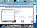
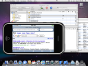
Once you have the iPhone SDK installed, you can run Xcode (from SpotLight) and launch a new project using a template just to try it out on the iPhone Simulator:
At this point you can develop your own iPhone applications and test them on the simulator. Also, if you joined the Apple developer program (the standard one is $99) you can test them in your iPhone as well.
If you’re planning to play around with the SDK I strongly recommend you to sign up on the iPhone Dev Center because there are lots of resources available: Getting started documents, videos, sample code, etc.