Some time back a new type of virtual port was introduced in OVN: external ports. The initial motivation was to support two main use cases in OpenStack:
- SR-IOV: For this type of workloads, the VM will bypass the hypervisor by accessing the physical NIC directly on the host. This means that the traffic sent out by the VM which requires a controller action (such as DHCP requests or IGMP traffic) will not hit the local OVN bridge and will be missed. You can read more about SR-IOV in this excellent blog post.
- Baremetal provisioning: Similarly, when provisioning a baremetal server, DHCP requests for PXE booting will be missed as those ports are not bound in OVN so even they’re sent in broadcast, all the ovn-controller instances in the cluster will ignore them.
For both cases we needed to have a way in OVN to process those requests coming from ports that are not bound to the local hypervisor and the solution was to implement the OVN external ports.
Testing scenario
From a pure OVN perspective, I created the following setup that will hopefully help understand the details and how to troubleshoot this type of ports.

- Two private networks:
- network1: 192.168.0.0/24 of type VLAN and ID 190
- network2: 192.168.1.0/24 of type VLAN and ID 170
- Two provider networks:
- external: 172.24.14.0/24 used for Floating IP traffic
- tenant: used by network1 and network2 VLAN networks
- One Logical router that connects both private networks and the Floating IP network
- router1-net1: “40:44:00:00:00:03” “192.168.0.1/24”
- router1-net2: “40:44:33:00:00:05” “192.168.1.1/24”
- router1-public: “40:44:00:00:00:04” “172.24.14.1/24”
- 4 Virtual Machines (simulated with network namespaces), 2 on each network
- vm1: addresses: [“40:44:00:00:00:01 192.168.0.11”]
- vm2: addresses: [“40:44:00:00:00:02 192.168.0.12”]
- vm3: addresses: [“40:44:33:00:00:03 192.168.1.13”]
- pext: addresses: [“40:44:44:00:00:10 192.168.1.111”]
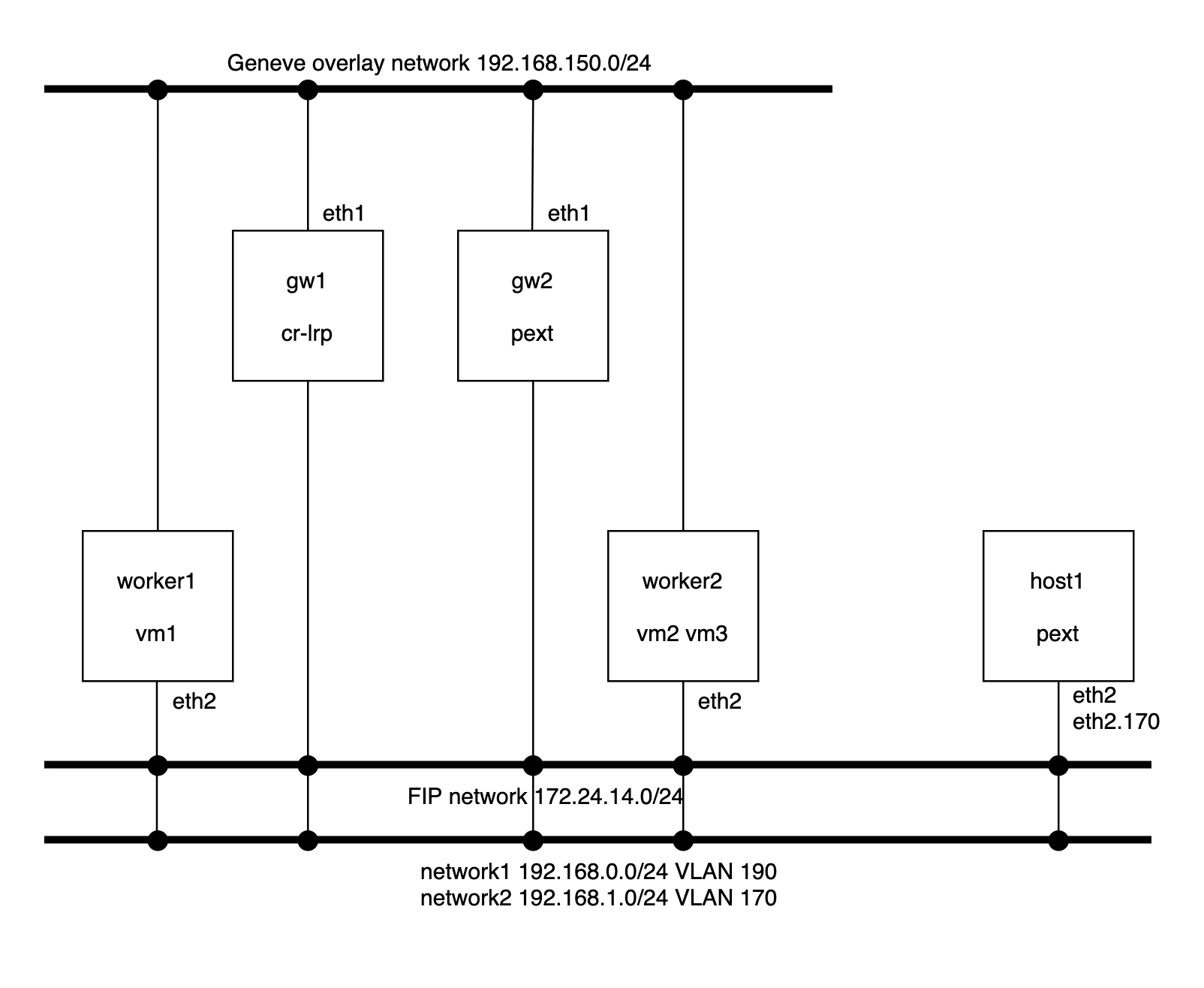
The physical layout involves the following nodes:
- Worker nodes:
- They have one NIC connected to the Geneve overlay network and another NIC on the provider network using the same OVS bridge (br-ex) for the flat external network and for both VLAN tenant networks.
- Gateway nodes:
- Same network configuration as the worker nodes
- gw1: which hosts the router gateway port for the Logical Router
- gw2: which hosts the external port (pext)
- Host
- This server is just another machine which has access to the provider networks and no OVN/OVS components are running on it.
- To illustrate different scenarios, during the provisioning phase, it’ll be configured with a network namespace connected to an OVS bridge and a VLAN device on the network2 (VLAN 170) with the MAC address of the external port.
A full vagrant setup can be found here that will deploy and configure the above setup for you in less than 10 minutes 🙂
The configuration of the external port in the OVN NorthBound database can be found here:
# Create the external port
ovn-nbctl lsp-add network2 pext
ovn-nbctl lsp-set-addresses pext \
          "40:44:44:00:00:10 192.168.1.111"
ovn-nbctl lsp-set-type pext external

# Schedule the external port in gw2
ovn-nbctl --id=@ha_chassis  create HA_Chassis \
          chassis_name=gw2 priority=1 -- \
          --id=@ha_chassis_group create \
          HA_Chassis_Group name=default2 \
          ha_chassis=[@ha_chassis] -- \
          set Logical_Switch_Port pext \
          ha_chassis_group=@ha_chassis_group
DHCP
When using a regular OVN port, the DHCP request from the VM hits the integration bridge and, via a controller action, is served by the local ovn-controller instance. Also, the DHCP request never leaves the hypervisor.
However, when it comes to external ports, the broadcast request will be processed by the chassis where the port is scheduled and the ovn-controller instance running there will be responsible of serving DHCP for it.
Let’s get to our setup and issue the request from host1:
[root@host1 vagrant] ip netns exec pext dhclient -v -i pext.170 --no-pid
Listening on LPF/pext.170/40:44:44:00:00:10
Sending on   LPF/pext.170/40:44:44:00:00:10
Sending on   Socket/fallback
DHCPREQUEST on pext.170 to 255.255.255.255 port 67 (xid=0x5149c1a3)
DHCPACK from 192.168.1.1 (xid=0x56bf40c1)
bound to 192.168.1.111 -- renewal in 1667 seconds.
Since we scheduled the external port on the gw2, we’d expect the request being handled there which we can check by inspecting the relevant logs:
[root@gw2 ~] tail -f /usr/var/log/ovn/ovn-controller.log
2020-09-08T09:01:52.547Z|00007|pinctrl(ovn_pinctrl0)
|INFO|DHCPACK 40:44:44:00:00:10 192.168.1.111
Below you can see the flows installed to handle DHCP in the gw2 node:
table=22, priority=100, udp, reg14=0x2, metadata=0x3, dl_src=40:44:44:00:00:10, nw_src=192.168.1.111, nw_dst=255.255.255.255, tp_src=68, tp_dst=67 actions=controller(…
table=22, priority=100, udp, reg14=0x2, metadata=0x3, dl_src=40:44:44:00:00:10, nw_src=0.0.0.0, nw_dst=255.255.255.255, tp_src=68, tp_dst=67 actions=controller(…
table=22, priority=100, udp, reg14=0x2, metadata=0x3, dl_src=40:44:44:00:00:10, nw_src=192.168.1.111, nw_dst=192.168.1.1, tp_src=68, tp_dst=67 actions=controller(…
Regular L2 traffic path
This is the easy path. As the external port MAC/IP addresses are known to OVN, whenever the packet arrives to the destination chassis via a localnet port they’ll be processed normally and delivered to the output port. No extra hops are observed:
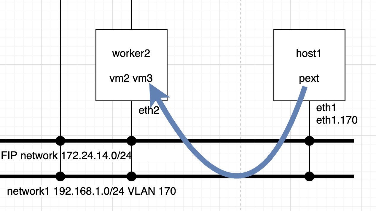
Let’s ping from the external port pext to vm3 which are in the same network. The expected path is for the ICMP packets to exit host1 from eth1 tagged with VLAN 170 and reach worker2 on eth2:
[root@host1 vagrant]# ip netns exec pext ping 192.168.1.13 -c2
PING 192.168.1.13 (192.168.1.13) 56(84) bytes of data.
64 bytes from 192.168.1.13: icmp_seq=1 ttl=64 time=0.331 ms
64 bytes from 192.168.1.13: icmp_seq=2 ttl=64 time=0.299 ms
— 192.168.1.13 ping statistics —
2 packets transmitted, 2 received, 0% packet loss, time 1000ms
rtt min/avg/max/mdev = 0.299/0.315/0.331/0.016 ms
Traffic from host1 arrives directly with the destination MAC address of the vm3 port and the reply is received from that same MAC:
[root@host1 ~]# tcpdump -i eth1 -vvnee
tcpdump: listening on eth1, link-type EN10MB (Ethernet), capture size 262144 bytes
14:45:22.919136 40:44:44:00:00:10 > 40:44:33:00:00:03, ethertype 802.1Q (0x8100), length 102: vlan 170, p 0, ethertype IPv4, (tos 0x0, ttl 64, id 14603, offset 0, flags [DF], proto ICMP (1), length 84)
192.168.1.111 > 192.168.1.13: ICMP echo request, id 19425, seq 469, length 64
14:45:22.919460 40:44:33:00:00:03 > 40:44:44:00:00:10, ethertype 802.1Q (0x8100), length 102: vlan 170, p 0, ethertype IPv4, (tos 0x0, ttl 64, id 13721, offset 0, flags [none], proto ICMP (1), length 84)
192.168.1.13 > 192.168.1.111: ICMP echo reply, id 19425, seq 469, length 64
At worker2, we see the traffic coming in from the eth2 NIC on the network2 VLAN 170:
[root@worker2 ~]# tcpdump -i eth2 -vvne
tcpdump: listening on eth2, link-type EN10MB (Ethernet), capture size 262144 bytes
14:43:33.009370 40:44:44:00:00:10 > 40:44:33:00:00:03, ethertype 802.1Q (0x8100), length 102: vlan 170, p 0, ethertype IPv4, (tos 0x0, ttl 64, id 22650, offset 0, flags [DF], proto ICMP (1), length 84)
192.168.1.111 > 192.168.1.13: ICMP echo request, id 19425, seq 360, length 64
14:43:33.009472 40:44:33:00:00:03 > 40:44:44:00:00:10, ethertype 802.1Q (0x8100), length 102: vlan 170, p 0, ethertype IPv4, (tos 0x0, ttl 64, id 23154, offset 0, flags [none], proto ICMP (1), length 84)
192.168.1.13 > 192.168.1.111: ICMP echo reply, id 19425, seq 360, length 64
Routed traffic path
In this example, we’re going to ping from the external port pext to vm1 (192.168.0.11) located in worker1. Now, the packet will exit the host1 with the destination MAC address of the router port (192.168.1.1). Since the traffic is originated by pext and it is bound to the gateway gw2, the routing will happen there.
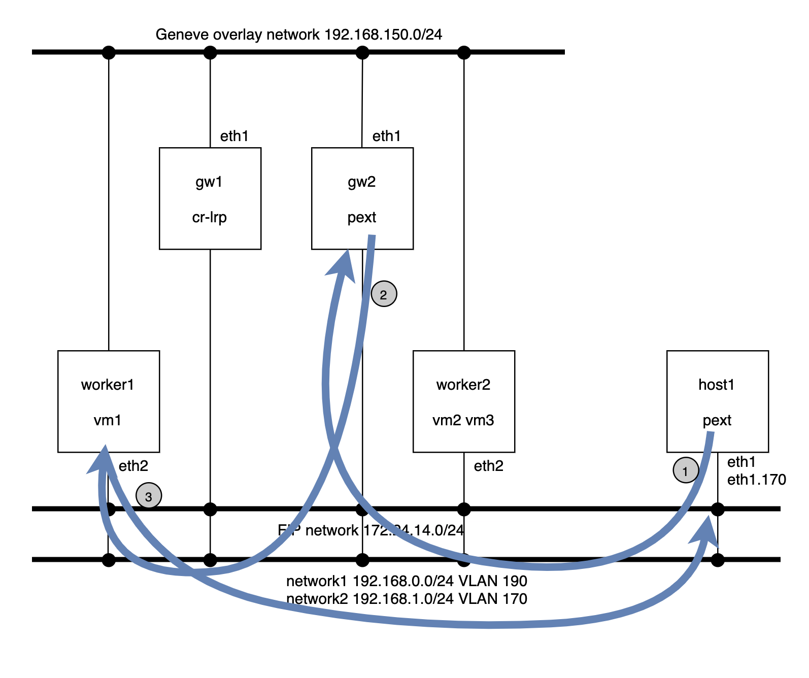
The router pipeline, and network1 and 2 pipelines will run in the gw2 and, from here, the packet goes out already to the network2 (VLAN 190) to worker1.
- Ping from external port pext to vm1:
[root@host1 ~]# ip netns exec pext ping 192.168.0.11 -c2
PING 192.168.0.11 (192.168.0.11) 56(84) bytes of data.
64 bytes from 192.168.0.11: icmp_seq=1 ttl=63 time=2.67 ms
64 bytes from 192.168.0.11: icmp_seq=2 ttl=63 time=0.429 ms
— 192.168.0.11 ping statistics —
2 packets transmitted, 2 received, 0% packet loss, time 1001ms
rtt min/avg/max/mdev = 0.429/1.553/2.678/1.125 ms
[root@host1 ~]# ip net e pext ip neigh
192.168.1.1 dev pext.170 lladdr 40:44:33:00:00:05 REACHABLE
[root@host1 ~]# tcpdump -i eth1 -vvnee
tcpdump: listening on eth1, link-type EN10MB (Ethernet), capture size 262144 bytes
16:18:52.285722 40:44:44:00:00:10 > 40:44:33:00:00:05, ethertype 802.1Q (0x8100), length 102: vlan 170, p 0, ethertype IPv4, (tos 0x0, ttl 64, id 15048, offset 0, flags [DF], proto ICMP (1), length 84)
192.168.1.111 > 192.168.0.11: ICMP echo request, id 1257, seq 6, length 64
- Packet arrives to gw2 for routing:
[root@gw2 ~]# tcpdump -i eth2 -vvne icmp
tcpdump: listening on eth2, link-type EN10MB (Ethernet), capture size 262144 bytes
16:19:40.901874 40:44:44:00:00:10 > 40:44:33:00:00:05, ethertype 802.1Q (0x8100), length 102: vlan 170, p 0, ethertype IPv4, (tos 0x0, ttl 64, id 41726, offset 0, flags [DF], proto ICMP (1), length 84)
192.168.1.111 > 192.168.0.11: ICMP echo request, id 1257, seq 56, length 64
- And from gw2, the packet is sent to the destination vm vm1 on the VLAN 190 network:
12:31:13.737551 40:44:44:00:00:10 > 40:44:33:00:00:05, ethertype 802.1Q (0x8100), length 102: vlan 170, p 0, ethertype IPv4, (tos 0x0, ttl 64, id 35405, offset 0, flags [DF], proto ICMP (1), length 84)
192.168.1.111 > 192.168.0.11: ICMP echo request, id 6103, seq 5455, length 64
12:31:13.737583 1e:02:ad:bb:aa:cc > 40:44:00:00:00:01, ethertype 802.1Q (0x8100), length 102: vlan 190, p 0, ethertype IPv4, (tos 0x0, ttl 63, id 35405, offset 0, flags [DF], proto ICMP (1), length 84)
192.168.1.111 > 192.168.0.11: ICMP echo request, id 6103, seq 5455, length 64
- At worker1, the packet is delivered to the tap port of vm1 and this will reply to the ping
[root@worker1 ~]# ip netns exec vm1 tcpdump -i vm1 -vvne icmp
tcpdump: listening on vm1, link-type EN10MB (Ethernet), capture size 262144 bytes
16:21:38.561881 40:44:00:00:00:03 > 40:44:00:00:00:01, ethertype IPv4 (0x0800), length 98: (tos 0x0, ttl 63, id 32180, offset 0, flags [DF], proto ICMP (1), length 84)
192.168.1.111 > 192.168.0.11: ICMP echo request, id 1278, seq 18, length 64
16:21:38.561925 40:44:00:00:00:01 > 40:44:00:00:00:03, ethertype IPv4 (0x0800), length 98: (tos 0x0, ttl 64, id 25498, offset 0, flags [none], proto ICMP (1), length 84)
192.168.0.11 > 192.168.1.111: ICMP echo reply, id 1278, seq 18, length 64
- The ICMP echo reply packet will be sent directly to pext through the localnet port to the physical network tagged with VLAN 170:
[root@host1 ~]# tcpdump -vvnne -i eth1 icmp
tcpdump: listening on eth1, link-type EN10MB (Ethernet), capture size 262144 bytes
12:35:00.322735 1e:02:ad:bb:aa:77 > 40:44:44:00:00:10, ethertype 802.1Q (0x8100), length 102: vlan 170, p 0, ethertype IPv4, (tos 0x0, ttl 63, id 18741, offset 0, flags [none], proto ICMP (1), length 84)
192.168.0.11 > 192.168.1.111: ICMP echo reply, id 6103, seq 5681, length 644
You might have noticed that the source MAC address (1e:02:ad:bb:aa:77) in the last step doesn’t correspond to any OVN logical port. This is because, in order for the routing to be distributed, OVN rewrites this MAC address to that of external_ids:ovn-chassis-mac-mappings. In our case, this tell us as well that the traffic is coming directly from worker1 saving the extra hop that we see for the pext -> vm1 path via gw2.
[root@worker1 ~]# ovs-vsctl get open . external_ids:ovn-chassis-mac-mappings
“tenant:1e:02:ad:bb:aa:77”
Floating IP traffic path
The FIP traffic path (for non Distributed Virtual Routing – DVR – case) is similar to the case that we just described except for the fact that since we require to traverse the distributed gateway port, our traffic will take an extra hop.
Example of ping from pext to the Floating IP of vm1 (172.24.14.100):
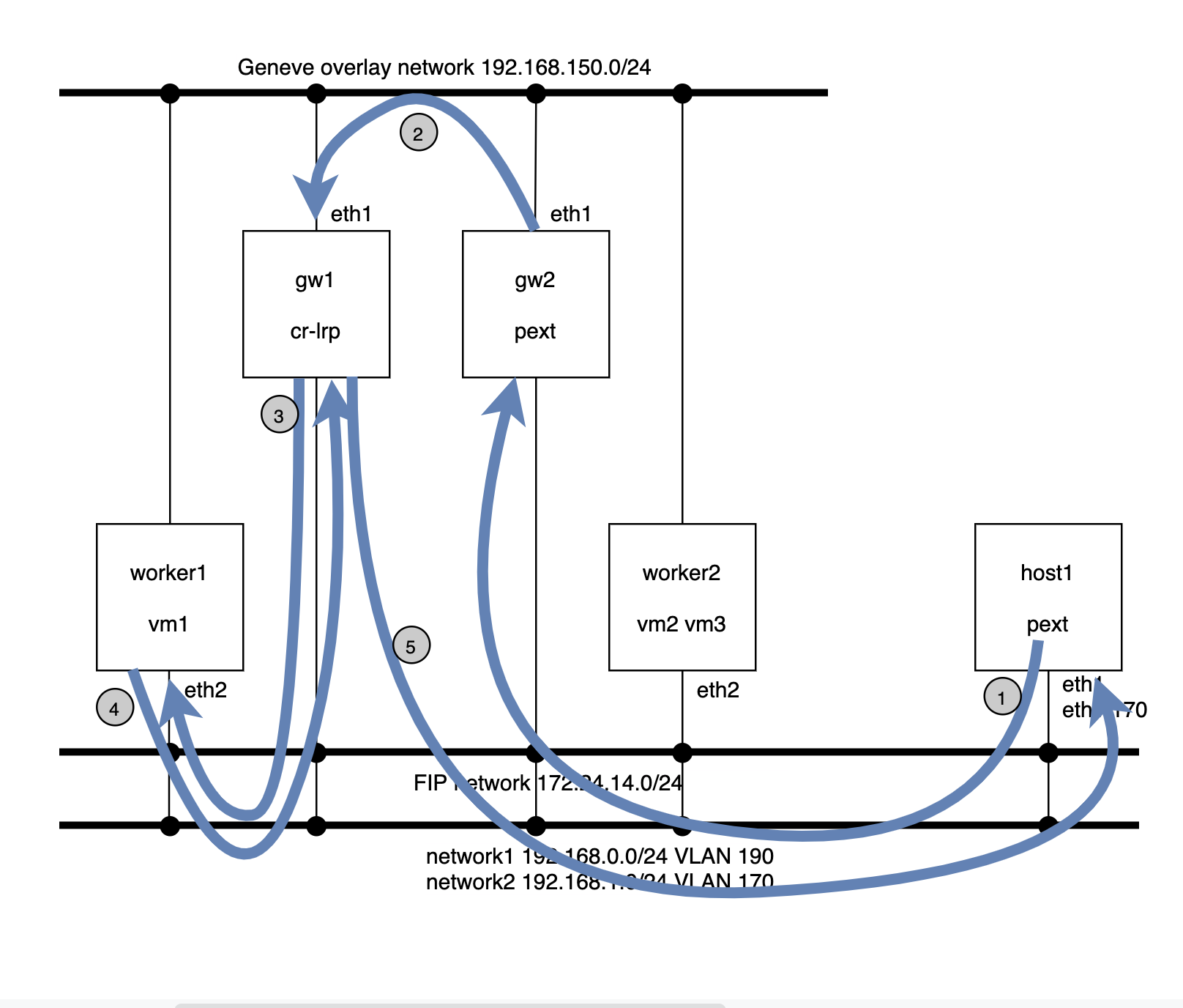
- The packet goes from host1 to gw2 via the VLAN 170 network with the destination MAC address of the network2 router port.
- From gw2, the traffic will be steered to the gw1 node which is hosting the distributed gateway port. This traffic is sent out via the Geneve overlay tunnel.
- gw1 will perform the routing and send the traffic to the FIP of vm1 via the public flat network (172.24.14.0/24) and src IP that of the SNAT (172.24.14.1).
- The request arrives to worker1 where ovn-controller un-NATs the packet to the vm1 (192.168.0.11) and delivers it to the tap interface. The reply from the vm1 is NATed to the FIP (172.14.14.100) and sent back to the router at gw1 via the flat network.
- gw1 will perform the routing to the network2 and push the reply packet directly onto the network2 with VLAN 190 which will be received at host1.
OpenStack
For use cases like SR-IOV workloads, OpenStack is responsible for creating an OVN port of type ‘external‘ in the NorthBound database and also its location, ie., which chassis are going to claim the port and install the relevant flows to, for example, serve DHCP.
This is done through a HA Chassis Group where the OVN Neutron plugin adds all the external ports to and, usually, the controller nodes belong to it. This way if one node goes down, all the external ports will be served from the next highest priority chassis in the group.
Information about how OpenStack handles this can be found here.
Future uses of OVN external ports include baremetal provisioning but as of this writing we lack some features like PXE chaining in OVN.